3D printed composite parts provide solution for UAV
New technology uses long carbon fibers to boost strength and stiffness for small yet high-performance aircraft.
Design Results:
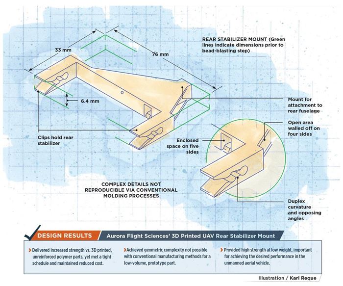
- Delivered increased strength vs. 3D printed, unreinforced polymer parts, yet met a tight schedule and maintained reduced cost.
- Achieved geometric complexity not possible with conventional manufacturing methods for a low-volume, prototype part.
- Provided high-strength at low weight, important for achieving the desired performance in the completed unmanned aerial vehicle.
Aurora Flight Sciences (Manassas, VA, US) is a well-known Tier 1 supplier of advanced aerospace components, such as the composite fuselage for the Global Hawk unmanned aerial vehicle (UAV). It is also a manufacturer of UAV platforms, including the line of small vertical takeoff and lift (VTOL) UAVs named GoldenEye; the Orion medium-altitude, long-endurance UAV; and the Skate, a family of small UAVs tailored for use in urban or crowded environments. In 2016, Aurora was selected by the Defense Advanced Research Projects Agency (DARPA, Arlington, VA, US) to develop the Vertical Take-Off and Landing Experimental Aircraft (VTOL X-Plane), which will be the first aircraft in history to demonstrate distributed hybrid-electric propulsion ducted fans, both tilt wing and canard, for VTOL and high efficiency in both hover and high-speed forward flight.
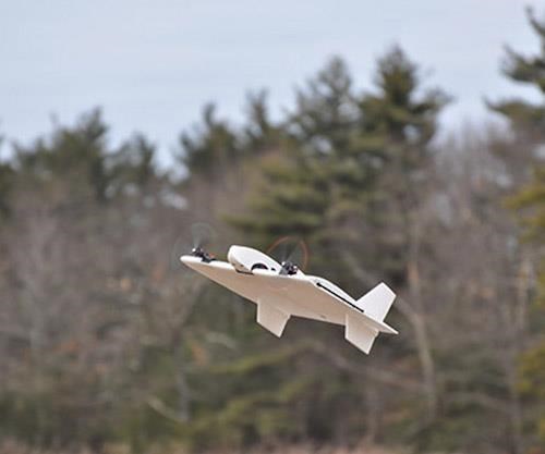
Aurora also is a pioneer in the use of 3D printing in aerospace systems. In November 2015, it worked with Stratasys Inc. (Eden Prairie, MN, US) to produce the world’s first jet-powered, 3D-printed UAV, using fused deposition modeling (FDM) and ULTEM 9085 polyetherimide (PEI) resin from SABIC (Pittsfield, MA, US) for 80% of its parts. According to Dan Campbell, structures research group lead at Aurora Flight Sciences R&D in Cambridge, MA, US, this project demonstrated “just how quickly you can go from designing to building to flying a 3D printed jet-powered aircraft.” Campbell adds that the overall design and build time for the 15-kg aircraft, which has a 3m wingspan, and can fly at speeds up to 240 kph, was reduced by 50% vs. conventional manufacturing methods.
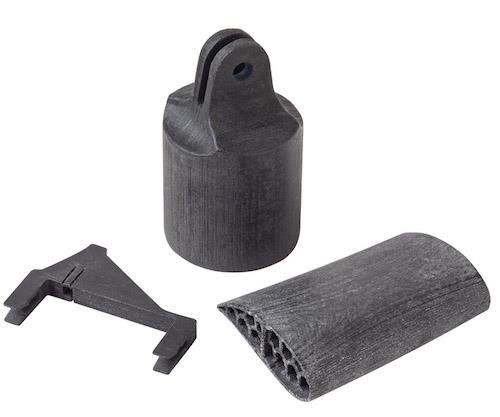
Aurora continues to work with a variety of 3D printing technologies, and recently pioneered the use of 3D-printed composite parts reinforced with 25.4-mm-long carbon fibers for a new-development UAV. Although that aircraft cannot be detailed here, its 76-mm by 38-mm rear stabilizer mount, which exploited the composites-based additive manufacturing (CBAM) technology developed by Impossible Objects (Northbrook, IL, US), provides an interesting study in what long-fiber reinforcement can provide in 3D-printed structures.
Fiber for higher strength
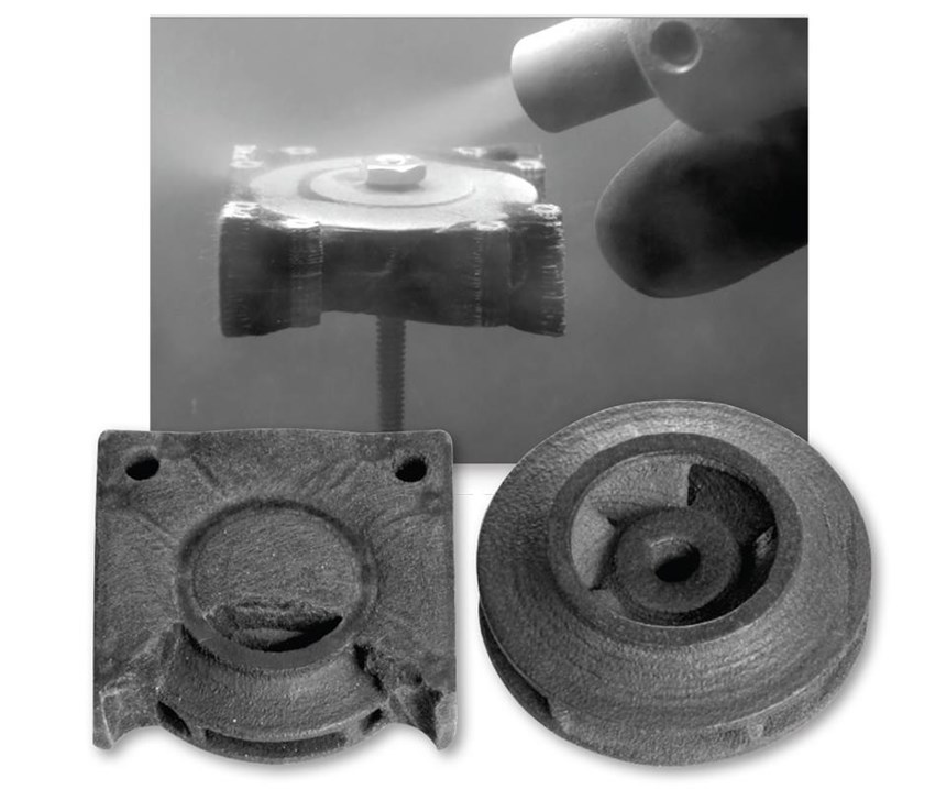
“This part sits below the tail at the rear of the aircraft,” explains Campbell. “The single projection mounts into the aircraft fuselage and the clothespin-shaped prongs or clips hold the stabilizer.” The part is an interior structure, not visible on the aircraft’s exterior.
Impossible Objects’ chief commercial officer Jeff DeGrange had worked with Aurora Flight Sciences in his previous tenure at Stratasys, and was in communication with Campbell’s team when they began having difficulty with this part. “The 3D printed unreinforced plastic parts they had been using were breaking,” recalls DeGrange. These parts were printed using selective laser sintering (SLS) and nylon resin. “This aircraft does not have landing gear,” explains Dan Campbell, “so when it lands on its belly, as it is designed to, the stabilizer receives a fair amount of loading, which would snap the prongs on the purely plastic parts.” DeGrange thought Impossible Objects’ CBAM technology could provide a solution.
“The part needed to be stronger,” recalls DeGrange, “but also lightweight.” This, indeed, is what CBAM offers because, as a 3D printing method, it departs from the ordinary with a rather uniquely designed process. It begins with nonwoven fabrics. Not only stronger than unreinforced plastics, the fabrics can accommodate a fiber length much longer than the milled/chopped fibers used in most commercially available “carbon fiber” FDM filaments.
“3D printing was obviously the quickest path to producing this part,” explains Impossible Objects CEO Larry Kaplan. He notes that the UAV rear stabilizer mount’s complex geometry could not have been easily injection molded or machined, “especially as an integrated, unitary part.” While most 3D printing processes enable rapid manufacture of low-volume, complex parts without tooling or significant subtractive metal parts-type machining, he adds, “ours was the only such technology that could provide a solution in this situation.”
Printing a CBAM part
Production of the part began with Impossible Objects’ review of the CAD-generated STL file supplied by Aurora Flight Sciences. (STL comes from STereoLithography, and is the standard software language for 3D printing.) “Sometimes the designs need to be refined for a layer-based manufacturing process like 3D printing,” explains Kaplan. He notes it is also important to look at where the part has its maximum and minimum strengths. “Our process achieves maximum strength in the plane of the fabric, so we collaborate with customers to maximize this per the part’s requirements,” he notes. Wall thicknesses also might need to be examined and, depending on the part design, increased for additional strength or even beneficially decreased to take advantage of the strength-to-weight ratio offered by a part printed with long fiber reinforcement.
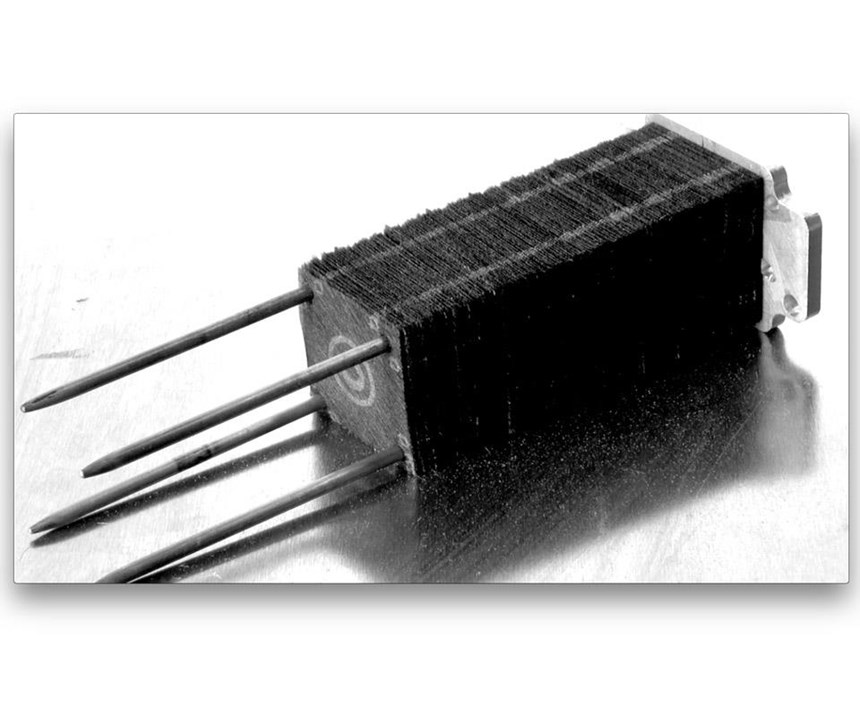
In this case, however, no adjustments were needed. Thus, Impossible Objects processed the design through its in-house software, slicing it into horizontal layers 0.05-0.08 mm thick, which were then sent to its printing equipment. “We then fed in the fabrics,” says Kaplan. For the rear stabilizer mount, the fabric was an isotropic nonwoven sheet made of carbon fibers chopped to nominal 25.4-mm length, held together with a binder. Sheets are processed individually, from the part bottom to its top.
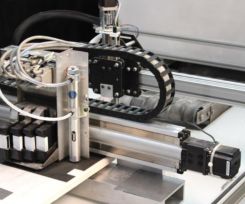
“Our printer applies a water-based solution to the sheet and then a powderized thermoplastic matrix,” says Kaplan, noting the mechanism is similar to a toner-based copier. This part used a high-density polyethylene (HDPE) powdered matrix. The powder adheres where the sheet is wet from printing. Only the part’s shape, layer by layer, is printed with the solution. Left dry are the areas of each layer where no material is needed for the final part.
Each powder-coated sheet then passes beneath a vacuum, which removes the non-wetted powder for reuse. The sheet is then stacked onto a processing bed fitted with upper and lower press platens. The next sheet is printed, powdered, vacuumed and stacked on top, followed by all the layers required for the part. Mechanical pins in the processing bed are used for registration of the layers. Holes for these pins are punched during the print process. “This produces very tight tolerances in the sheet positioning,” says Kaplan, “to within 0.025 mm or tighter.”
When all of the sheets are stacked, they are heated to the melt temperature of the thermoplastic polymer, which in this case was roughly 135°C. The processing bed’s platens compress the stack to final part thickness — under the resulting heat and pressure, the carbon fibers are encapsulated in the thermoplastic polymer matrix. At this point, however, the now-consolidated reinforced polymer is still surrounded by the portion of the fiber layers that were previously vacuumed free of thermoplastic powder. “We then use bead blasting to remove the excess, uncoated fibers,” explains Kaplan, “leaving the final part.”
At the time the rear stabilizer mount was first built with CBAM, more than 18 months ago, production took about 30 minutes, on average, per part batch. “Today, we can do this part in an average of 15 minutes,” says Kaplan. “We have drastically improved our processing times and we batch process so that heat and press time is shared between multiple parts.” Impossible Objects also is working on additional improve- ments, which it claims will ultimately reduce the part’s processing time to several minutes or even less.
“Another key benefit of the Impossible Objects process is that it is based on existing fiber materials and polymers,” Kaplan points out. “This was important for this project because of time constraints.” Since then, Kaplan’s team has proven that the system can work with nylon (PA12) and polyetheretherketone (PEEK), which offers new end-uses. Glass and aramid fiber materials also can be processed.
Stronger, faster and multifunctional
Impossible Objects has tested CF/HDPE flat specimens, which Kaplan says are made in the same way and at the same speed as the production UAV parts, so they indeed reflect printed part quality, and obtained tensile strengths of 150 MPa and tensile modulus of 10 GPa. For CF/PEEK test specimens, it has measured tensile strength of 205 MPa and modulus of 12 GPa. “Compared to published properties of standard, unreinforced 3D-printed nylon and HDPE parts, we’re up to 10 times stronger,” Kaplan asserts. “Parts printed from Ultem [PEI] are the closest in properties, but are still less than half of what we can produce using CBAM.”
Although this project achieved success in a low-volume, functional part application, Kaplan says Impossible Objects is headed toward serial production of parts in aircraft, automobiles, medical devices/implants and high-performance sporting goods. “Our technology offers advantages in both speed and material properties vs. other 3D printing,” he contends. “We can also use a wide range of materials, for example nonwovens with metals or coated fibers.” This ability to integrate augmented electrical conductivity opens up applications like electromagnetic interference (EMI) shielding for electronics. “There is a huge market in EMI shields where you can tailor the properties,” says Kaplan. He adds that with CBAM, it is possible to alternate layers of glass and carbon fiber, “so you now have insulating and conducting layers within the same part.”
For Aurora’s Campbell, this part was a demonstration of what carbon fiber can offer in 3D printed parts. But it also points the way for progress in the future. “Continuous carbon fiber is a must in modern day aircraft,” he contends. “You really cannot beat the properties it offers for the weight.” He says the ultimate goal, then, is to use 3D printing to fabricate primary structures, using continuous carbon fiber. “It’s definitely where we want to end up.”
Related Content
Cryo-compressed hydrogen, the best solution for storage and refueling stations?
Cryomotive’s CRYOGAS solution claims the highest storage density, lowest refueling cost and widest operating range without H2 losses while using one-fifth the carbon fiber required in compressed gas tanks.
Read MorePEEK vs. PEKK vs. PAEK and continuous compression molding
Suppliers of thermoplastics and carbon fiber chime in regarding PEEK vs. PEKK, and now PAEK, as well as in-situ consolidation — the supply chain for thermoplastic tape composites continues to evolve.
Read MoreTU Munich develops cuboidal conformable tanks using carbon fiber composites for increased hydrogen storage
Flat tank enabling standard platform for BEV and FCEV uses thermoplastic and thermoset composites, overwrapped skeleton design in pursuit of 25% more H2 storage.
Read MoreCarbon fiber, bionic design achieve peak performance in race-ready production vehicle
Porsche worked with Action Composites to design and manufacture an innovative carbon fiber safety cage option to lightweight one of its series race vehicles, built in a one-shot compression molding process.
Read MoreRead Next
All-recycled, needle-punched nonwoven CFRP slashes carbon footprint of Formula 2 seat
Dallara and Tenowo collaborate to produce a race-ready Formula 2 seat using recycled carbon fiber, reducing CO2 emissions by 97.5% compared to virgin materials.
Read MoreDeveloping bonded composite repair for ships, offshore units
Bureau Veritas and industry partners issue guidelines and pave the way for certification via StrengthBond Offshore project.
Read More“Structured air” TPS safeguards composite structures
Powered by an 85% air/15% pure polyimide aerogel, Blueshift’s novel material system protects structures during transient thermal events from -200°C to beyond 2400°C for rockets, battery boxes and more.
Read More

