
Best practices for V-notched shear testing of composites
In my October 2015 column, I wrote an overview of the widely used V-notched shear test methods for composite materials. In this column, we focus on some additional best practices when performing V-notched shear testing of fiber-reinforced composites.

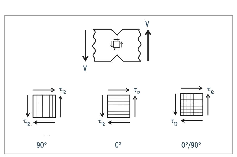
Fig. 1
Central test section of V-notched shear specimen and possible laminate orientations. Source, all images | Dan Adams
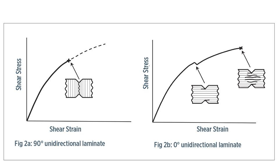
Fig. 2
Premature failures in unidirectional specimens
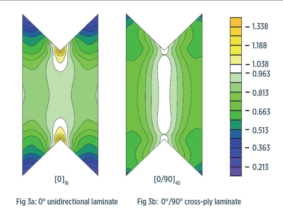
Fig. 3
Normalized shear stress and shear strain distributions5.


In my October 2015 column, I wrote an overview of the widely used V-notched shear test methods for composite materials:
• The V-notched beam “Iosipescu” shear test, ASTM D 5379.1


• The V-notched rail shear test, ASTM D 7078.2
• The V-notched combined loading shear test.
There are important differences among these three test methods. These include the specimen size and the loading method (edge loading, face loading or both). However, all three methods feature the same V-notched test section with opposing 90° notches machined to a depth that is 20-23% of the full specimen width (Fig. 1). is reduced cross-sectional area between the notches produces the highest shear stresses and, therefore, specimen failure in the central test section.
Although the increase in shear stress due to the notched test section is easy to understand, the use of V-notches to produce a uniform shear stress state is less obvious. The presence of notches is generally associated with stress concentrations, and, in fact, the V-notches shown in Fig. 1 would produce significant stress concentrations if the notched specimen were axially loaded in tension or compression. Under shear loading, however, the 90° V-notches do not produce significant stress concentrations. They, in fact, significantly increase the uniformity of the shear stress distribution compared to unnotched specimens. Without notches, the shear stress has a parabolic distribution across the specimen width, ranging in magnitude from zero at the outer edges to a maximum at the horizontal midplane. The high uniformity achieved with V notches, coupled with a higher magnitude of shear stress in the central test section between the V-notches is highly desirable for accurate shear modulus and shear strength measurements of composites. In this column, we focus on some additional best practices when performing V-notched shear testing of fiber-reinforced composites.
Perhaps the most important consideration for V-notched shear testing is the choice of composite laminate used to measure the in-plane shear modulus, G12, and shear strength, S12. Because these quantities are known to be lamina or unidirectional laminate properties, it’s not surprising that unidirectional composite laminates are commonly used for testing. Additionally, because shear stresses act on the horizontal and vertical planes (Fig. 1), either a 0° (horizontal) or 90° (vertical) fiber orientation may be used. Therefore, in theory, the two fiber orientations should produce the same results. However, the 90° fiber orientation is rarely used because even a small stress concentration at the notch tips, or a crack produced during specimen preparation or handling, can lead to a sudden, premature failure (Fig. 2a). The use of a 0° fiber orientation is a better choice because the horizontal fiber orientation eliminates the weak vertical plane between the notches. However, the 0° fiber orientation produces a small stress concentration at the notch tips due to the significant material orthotropy — the large difference in stiffness between the horizontal (E1) and vertical (E2) directions.
These notch-tip stress concentrations, coupled with the weak horizontal planes in the specimen, can result in the formation of short horizontal cracks that form at the notch tips and produce a small load drop (Fig. 2b). Although these notch-tip cracks and the associated load drop were of concern during the development of the original V-notched beam test, they were found to not significantly affect the measured values of G12 or S12.3 Rather, the notch-tip cracks relieved the stress concentration produced in the 0° unidirectional specimens and permitted further loading until shear failure occurred in the specimen test section.
A less obvious candidate laminate for measuring the in-plane shear properties G12 and S12 is a cross-ply laminate, consisting of 0° and 90° plies. As shown in Fig. 1, the 0° and 90° plies are subjected to the same state of shear stress, as if they were part of a unidirectional laminate. Thus, in theory, a cross-ply laminate should produce the same result as either of the unidirectional laminates under pure shear loading.
However, there are significant advantages to using a [0/90]ns cross-ply laminate for in-plane shear testing. For starters, cross-ply specimens do not have a weak plane that exists in the unidirectional laminates. Thus, they are significantly less fragile and do not experience the premature cracking that occurs when using either the 0° or 90° unidirectional laminates. Additionally, cross-ply laminates do not have the high orthotropy ratio of the unidirectional laminates and consequently produce a more uniform distribution of shear stress and shear strain in the notched test section of the specimen, and minimal stress concentration at the notch tips. While desirable features for the accurate measurement of S12, they are even more important for measuring G12 during the initial stage of loading. The shear modulus is calculated using the formula:
Note that the average shear stress,τ12, is used in this equation, calculated as the applied shear force divided by the specimen cross-sectional area between the notches. Thus, to produce the correct value of G12, the average value of shear strain, γ12, also must be used. For strain gages to measure this average shear strain value, they must be located within regions of the specimen test section in which this average shear strain exists. In Fig. 3, this region corresponds to the white-colored regions, in which the shear strain is close to the average notch-to-notch value. For the cross-ply laminate (Fig. 3b), a suitable region of average shear strain is present in a relatively large region centered between the V-notches. For a 0° carbon/epoxy specimen (Fig. 3a), however, the shear strain in the central region of the specimen is approximately 10% lower than the average value, with this central value dependent upon the orthotropy ratio (E1/E2) of the material being tested.
Using this lower value of shear strain in the above equation will result in a calculated G12 value about 10% greater than the correct value, even when all other aspects of the test are performed properly. This error, produced by using conventional strain gages in the central region of the 0° unidirectional specimen, may be eliminated by using specialized shear strain gages that are of narrow rectangular shape and extend from notch tip to notch tip, allowing for the average shear strain to be obtained over the nonuniform area. However, such shear strain gages are currently available only for the smaller V-notched beam (ASTM D 5379) specimen4. Thus for measuring the in-plane shear modulus G12 and shear strength S12 of composite materials, the use of cross-ply laminates consisting of 0° and 90° plies is recommended.
References
1ASTM D 5379/D 5379 M-12, “Standard Test Method for Shear Properties of Composite Materials by the V-Notched Beam Method,” ASTM International (W. Conshohocken, PA, US), 2012 (first issued in 1993).
2ASTM D 7078/D 7078 M-12, “Standard Test Method for Shear Properties of Composite Materials by the V-Notched Rail Shear Method,” ASTM International (W. Conshohocken, PA, US), 2012 (first issued in 2005).
3D.F. Adams and E. Q. Lewis, “Experimental Strain Analysis of the losipescu Shear Test Specimen,” Experimental Mechanics, Vol. 35 No. 3, 1995, pp. 352-360.
4“Plane-Shear Measurement with Strain Gages,” Vishay Precision Group Tech Note TN-512-1, Document No. 11062, September 2010, online at www.vishaypg.com/docs/11062/tn5121tn.pdf
5D.O. Adams, J.M. Moriarty, A.M. Gallegos, and D.F. Adams, “Development and Evaluation of the V-Notched Rail Shear Test for Composite Laminates,” Federal Aviation Administration Report No. DOT/FAA/AR-03/63, September 2003


.jpg;maxWidth=300;quality=90;format=webp)


Related Content

ATLAM combines composite tape laying, large-scale thermoplastic 3D printing in one printhead
CEAD, GKN Aerospace Deutschland and TU Munich enable additive manufacturing of large composite tools and parts with low CTE and high mechanical properties.
Read More
Optimized approach to predict delamination failure in CFRTP structures
ARRK Engineering and Mitsui Chemicals improved delamination prediction accuracy to help optimize absorbed energy/failure load for an overmolded TAFNEX CF/PP UD tape bumper beam.
Read More
Composite sidewall cover expands options for fire-safe rail components
R&D project by CG Rail explores use of carbon fiber-reinforced thermoplastics and recycled manufacturing scrap to meet fire safety, weight and volume targets.
Read More
Active core molding: A new way to make composite parts
Koridion expandable material is combined with induction-heated molds to make high-quality, complex-shaped parts in minutes with 40% less material and 90% less energy, unlocking new possibilities in design and production.
Read MoreRead Next

“Structured air” TPS safeguards composite structures
Powered by an 85% air/15% pure polyimide aerogel, Blueshift’s novel material system protects structures during transient thermal events from -200°C to beyond 2400°C for rockets, battery boxes and more.
Read More
VIDEO: High-rate composites production for aerospace
Westlake Epoxy’s process on display at CAMX 2024 reduces cycle time from hours to just 15 minutes.
Read More
Modeling and characterization of crushable composite structures
How the predictive tool “CZone” is applied to simulate the axial crushing response of composites, providing valuable insights into their use for motorsport applications.
Read More