Fiber-matrix interfacial bond test methods
Dr. Don Adams describes six single-fiber methods for testing fiber-matrix interfacial bond strength.
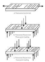
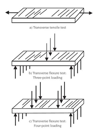
In my previous column (see “Editor's Picks,” at right), I discussed transverse flexural testing of a unidirectional composite as one method of evaluating the strength of the fiber/matrix interfacial bond. I noted then that, as an alternative, one also may use any of several single-fiber interfacial bond test methods.
Although some single-fiber test methods were known previously, reports of the most extensive development work were published between 1985 and 1995. Many new fibers and polymer matrix materials were introduced during the 1980s, and test methods were needed to evaluate the new fiber/matrix interface combinations.
Primary examples of single-fiber interfacial bond tests are shown in Fig. 1. Common to all is a significant amount of data scatter in the experimental results. This is generally attributed to the presence of naturally occurring random fiber flaws and the lack of uniformity in the surface characteristics along the length of each fiber. Usually, a large number of replicates (typically dozens) must be tested to obtain a statistically significant average value for interfacial bond strength. Further, manipulating very small-diameter single fibers is painstaking and time consuming. In contrast, when an actual composite is tested, these local variations in interfacial bond strength are averaged over a large volume of material, resulting in much less data scatter.
However, a test of a composite typically only infers the strength of the interfacial bond because it does not directly measure this property. The desire for a means to measure interfacial bond strength directly continues to stimulate the use of single-fiber test methods.
No standard test methods exist. Consequently, the specific details of how to perform each test vary from one investigator to another. That said, there are general procedures for each method, as follows.
Embedded single-fiber tension (Fig. 1a): This test determines the shear strength of the interface. A single fiber oriented along the specimen axis is molded into a thin, flat, dog-boned specimen of matrix material. The specimen is typically cast in an open-faced silicone rubber mold. Usually, multiple-cavity molds (10 to 20 cavities or more) are used to accommodate a large number of replicate specimens. The matrix must be ductile enough to absorb, without fracturing, the energy released when the fiber breaks locally under the applied tensile load (local matrix cracking is acceptable). The loading is continued and additional fiber breaks occur until the specimen fractures. The procedure can be observed under polarized light in a microscope. The fiber breaks and debonding along the interface are readily visible. If a transparent matrix is not used, the specimen is simply loaded to failure, the matrix is digested away and the lengths of fiber fragments are measured.
The principle is that the fiber will continue to fragment into shorter and shorter lengths until they are too short to develop tensile stresses via shear transfer from the matrix sufficient to further fracture the fiber. This “critical length” is then used to calculate the interfacial shear strength, knowing the tensile strength of the fiber.
Embedded single-fiber compression (Fig. 1b): This is an interface tensile strength test method. When the single-fiber specimen is loaded in compression, a tensile normal stress is developed at the interface due to the Poisson effect. By observing the specimen as the load is increased, interfacial debonding is evident when light refracts off of the free surface that is created. Then the interface tensile stress can be calculated. This test method was introduced to the composites community almost 50 years ago. It has not been used extensively, but not because of any particular deficiency in the method itself. As I noted in November, interfacial shear strength has always generated more interest than interfacial tensile strength.
Microdebond (Fig. 1c): This method was developed in the late 1970s, and although it is a single-fiber test, it does use an actual composite. The unidirectional composite is sectioned normal to the fiber direction, polished and then placed in a specially equipped optical microscope fitted with a microprobe. This probe, centered on an individual fiber, loads the fiber in compression to cause debonding of the fiber from the surrounding matrix at the surface. Then an analysis is performed to calculate the stresses at the interface when it fails. Commercial units that automate the process are available, making the method attractive in some situations.
Single-fiber push-out (Fig. 1d): Although it is used infrequently, this interfacial shear strength test should be noted. Unlike the microdebond specimen, which can be thick, the specimen for the single-fiber push-out test is a very thin, polished section of a unidirectional composite. Individual fibers are pushed out, again using a microprobe. The interfacial shear strength is calculated as the force required to push out a fiber divided by the interfacial bond area.
Single-fiber pull-out (Fig. 1e): In this interfacial shear strength test, a single fiber is fully embedded (typically with both ends protruding from the surfaces, as shown) in a thin sheet or film of matrix material. The force required to pull the fiber out of the film is determined, and the corresponding interfacial shear strength is calculated. For small-diameter fibers that exhibit high interfacial bond strengths — typical of those used in high-performance composites — the matrix film might have to be extremely thin (e.g., 0.05 mm/0.002 inch thick) so the fiber will pull out before it breaks. Because it is difficult to prepare such thin specimens, this method has given way somewhat to the following method.
Microbond test (Fig. 1f): Developed in the mid-1980s, this method also tests interfacial shear strength. It is sometimes termed the bead pull-off test to clearly distinguish it from the microdebond test. A bead (drop) of matrix material is cured in place on an individual fiber. Then the bead is restrained by opposing knife edges (as shown) and stripped off when a tensile force is applied to the fiber. The interfacial shear strength is the force divided by the embedded area of the fiber. The bead must be small enough to permit the fiber to pull out rather than break. Typically, bead diameters in the 100 to 200 μm range are suitable.
In summary, the embedded single-fiber tension test (Fig. 1a) and the microbond (bead pull-off) test (Fig. 1f), which are interfacial shear methods, are most commonly used. The microbond test is the easiest to perform.
Related Content
Improving carbon fiber SMC simulation for aerospace parts
Simutence and Engenuity demonstrate a virtual process chain enabling evaluation of process-induced fiber orientations for improved structural simulation and failure load prediction of a composite wing rib.
Read MoreATLAM combines composite tape laying, large-scale thermoplastic 3D printing in one printhead
CEAD, GKN Aerospace Deutschland and TU Munich enable additive manufacturing of large composite tools and parts with low CTE and high mechanical properties.
Read MoreAutomated robotic NDT enhances capabilities for composites
Kineco Kaman Composites India uses a bespoke Fill Accubot ultrasonic testing system to boost inspection efficiency and productivity.
Read MoreCarbon fiber, bionic design achieve peak performance in race-ready production vehicle
Porsche worked with Action Composites to design and manufacture an innovative carbon fiber safety cage option to lightweight one of its series race vehicles, built in a one-shot compression molding process.
Read MoreRead Next
Transverse flexure testing
Dr. Donald Adams examines test methods for determining the transverse tensile strength of a composite formed from unidirectional plies.
Read MoreDeveloping bonded composite repair for ships, offshore units
Bureau Veritas and industry partners issue guidelines and pave the way for certification via StrengthBond Offshore project.
Read More“Structured air” TPS safeguards composite structures
Powered by an 85% air/15% pure polyimide aerogel, Blueshift’s novel material system protects structures during transient thermal events from -200°C to beyond 2400°C for rockets, battery boxes and more.
Read More


