The making of glass fiber
The old art behind this industry’s first fiber reinforcement is explained,with insights into new fiber science and future developments.

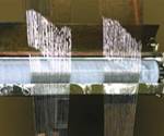
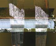
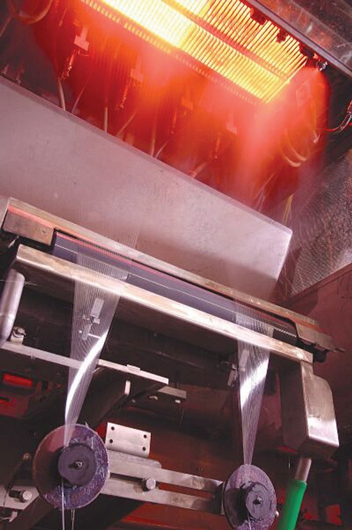
Glass fiber was the first reinforcement used in modern polymeric composites but springs from an ancient art. Here, glass fiber ends are wound side-by-side onto warp beams (large rolls or cylinders) which will be used later in a fiberglass fabric-weaving operation. Source | AGY
Fiberglass is the original fiber reinforcement of modern composites. Though the ancient Phoenicians, Egyptians and Greeks knew how to melt glass and stretch it into thin fibers, it wasn’t until the 1930s that the process evolved into commercial-scale manufacturing of continuous fibers, which would later be used as structural reinforcements.
Patent applications filed between 1933 and 1937 by Games Slayter, John Thomas and Dale Kleist, employees of Owens-Illinois Glass Co. (Toledo, Ohio), record the key developments that step-changed the industry from producing discontinuous-fiber glass wool to making continuous glass filaments with diameters as small as 4 microns (4 millionths of a meter) and thousands of feet long. Ensuing breakthroughs made the process commercially viable and cost-competitive.
The last two patents from this series, entitled “Textile Material” and “Glass Fabric,” foreshadowed the future of glass fiber as a textile reinforcement. The patents were awarded in 1938, the same year that Owens-Illinois and Corning Glass Works (Corning, N.Y.) joined to form Owens-Corning Fiberglas Corp. (OCF). The new company marketed its glass fiber under the trade name Fiberglas, which was the genesis of the common generic reference to fiberglass. It was not long before a number of other manufacturers entered the market and, through numerous process and product innovations, contributed to a worldwide structural composite reinforcements market, that according to market research firm Lucintel (Dallas, Texas, U.S.), reached 2.5 billion pounds in 2018.
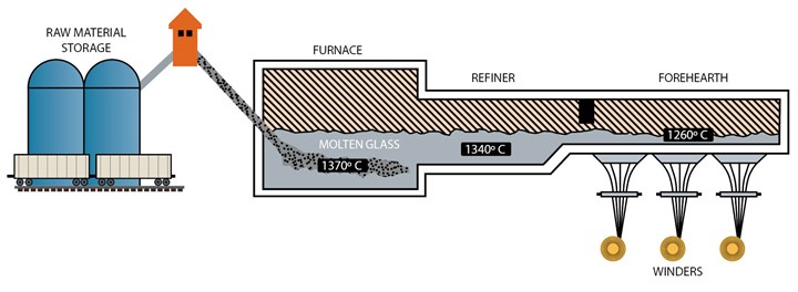
Glass fiber is made by blending raw materials, melting them in a three-stage furnace furnace, extruding the molten glass through a bushing in the bottom of the forehearth, cooling the filaments with water and then applying a chemical size. The filaments then are gathered and wound into a package. Source | OCV
The glass fiber process
Textile-grade glass fibers are made from silica (SiO2) sand, which melts at 1720°C/3128°F. SiO2 is also the basic element in quartz, a naturally occurring rock. Quartz, however, is crystalline (rigid, highly ordered atomic structure) and is 99% or more SiO2. If SiO2 is heated above 1200°C/2192°F then cooled ambiently, it crystallizes and becomes quartz. Glass is produced by altering the temperature and cooldown rates. If pure SiO2 is heated to 1720°C/3128°F then cooled quickly, crystallization can be prevented and the process yields the amorphous or randomly ordered atomic structure we know as glass.
Although continuously refined and improved, today’s glass fiber manufacturers combine this high heat/quick cool strategy with other steps in a process that is basically the same as that developed in the 1930s, albeit on a much larger scale. This process can be broken down into five basic steps: batching, melting, fiberization, coating and drying/packaging.
Step 1: Batching
Although a viable commercial glass fiber can be made from silica alone, other ingredients are added to reduce the working temperature and impart other properties that are useful in specific applications.
For example, E-glass, originally aimed at electrical applications, with a composition including SiO2, AI2O3 (aluminum oxide or alumina), CaO (calcium oxide or lime) and MgO (magnesium oxide or magnesia), was developed as a more alkali-resistant alternative to the original soda lime glass. Later, boron was added via B2O3 (boron oxide) to increase the difference between the temperatures at which the E-glass batch melted and at which it formed a crystalline structure to prevent clogging of the nozzles used in fiberization (Step 3, below).
S-glass fibers, developed for higher strength, are based on a SiO2-AI2O3-MgO formulation but contain higher percentages of SiO2 for applications in which tensile strength is the most important property.
In the initial stage of glass manufacture, therefore, these materials must be carefully weighed in exact quantities and thoroughly mixed (batched). Batching has become automated, using computerized weighing units and enclosed material transport systems. For example, in Owens Corning’s plant in Taloja, India, each ingredient is transported via pneumatic conveyors to its designated multistory storage bin (silo), which is capable of holding 70 to 260 ft³ (1.98 to 7.36m³) of material. Directly beneath each bin is an automated weighing and feeding system, which transfers the precise amount of each ingredient to a pneumatic blender in the batch house basement.
Step 2: Melting
From the batch house, another pneumatic conveyor sends the mixture to a high temperature (≈1400ºC/2552ºF) natural gas-fired furnace for melting. The furnace is typically divided into three sections, with channels that aid glass flow. The first section receives the batch, where melting occurs and uniformity is increased, including removal of bubbles. The molten glass then flows into the refiner, where its temperature is reduced to 1370ºC/2500ºF. The final section is the forehearth, beneath which is located a series of four to seven bushings that, in the next step, are used to extrude the molten glass into fibers. Large furnaces have several channels, each with its own forehearth.
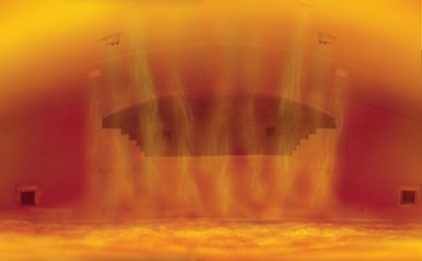
This direct melt furnace at OCV’s reinforcements plant in Amarillo, Texas processes 30,000 tonnes of molten glass per year via nine burners which operate more efficiently by using oxygen, instead of air, to help the natural gas fuel burn hotter and cleaner. Source | OCV
According to Scott Northrup, global business development director for AGY (Aiken, S.C.), furnace operation is being improved on several fronts. The use of larger furnaces has increased throughput to between 30,000 and 40,000 metric tonnes (66.2 to 88.2 million pounds) per year. One of the most important advances has been digital control technology. “Digital controls ... measure and manage the precise temperature of the glass as it moves through the furnace as well as the gas ... and oxygen flow rates.” They also maintain a smoother, steadier flow to the fiberization equipment, avoiding air bubbles or other interruptions that could cause discontinuities in fiber formation. Control of oxygen flow rates are crucial because furnaces that use the latest technology burn nearly pure oxygen instead of air because it helps the natural gas fuel to burn cleaner and hotter, melting glass more efficiently. It also lowers operating costs by using less energy and reduces nitrogen oxide (NOx) emissions by 75% and carbon dioxide (CO2) emissions by 40%.
Because the furnace is a consumable — the process of melting and moving the glass wears away the refractory bricks that line the furnace interior — efforts are being made to increase the brick’s service life. Glass fiber production is a continuous process, says AGY sales and marketing VP Drew Walker, “Once production begins, you don’t shut it down.” Manufacturers say that a typical furnace averages 12 to 15 years between rebuilds, with seven years as a worst-case scenario. Walker explains that at up to $150 million for construction of a new manufacturing site and $10 million to $15 million for a new furnace or rebuild, extending furnace life translates directly into dollars.
The industry takes three main approaches to glass melting: (1) indirect melt (also called marble remelt); (2) direct melt using larger-scale furnaces (8,000 to 100,000 metric tonnes per year); and (3) direct melt using smaller-scale furnaces (150 to 200 metric tonnes per year), which are also called paramelters. For indirect marble remelt, molten glass is sheared and rolled into marbles roughly 0.62 inch (15 to 16 millimeters) in diameter, which are cooled, packaged and then transported to a fiber manufacturing facility where they are remelted for fiberization (see “Step 3”). The marbles facilitate visual inspection of the glass for impurities, resulting in a more consistent product. The direct melt process transfers molten glass in the furnace directly to fiber-forming equipment. Because direct melting eliminates the intermediate steps and the cost of forming marbles, it has become the most widely used method.
Step 3: Fiberization
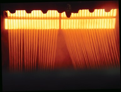
Molten glass exits the furnace at ≈1340°C/2444°F and is extruded through heated bushing plates (top image), which have 200 to 8,000 very small orifices, or nozzles. The winders (lower part of bottom image) apply tension to the extruded glass, drawing it out into thin filaments. These are cooled by water spray (the mist can be seen near the top of the bottom image), coated with size (via the roller) and gathered together to form a strand. Source | OCV (top) and PPG (bottom)
Glass fiber formation, or fiberization, involves a combination of extrusionand attenuation. In extrusion, the molten glass passes out of the forehearth through a bushing made of an erosion-resistant platinum/rhodium alloy with very fine orifices, from 200 to as many as 8,000. Bushing plates are heated electronically, and their temperature is precisely controlled to maintain a constant glass viscosity. Water jets cool the filaments as they exit the bushing at roughly 1204ºC/2200ºF. Attenuation is the process of mechanically drawing the extruded streams of molten glass into fibrous elements called filaments, with a diameter ranging from 4 to 34 micrometers (one-tenth the diameter of a human hair). A high-speed winder catches the molten streams and, because it revolves at a circumferential speed of ~2 miles/~3 kilometers per minute (much faster than the molten glass exits the bushings), tension is applied, drawing them into thin filaments.
The bushings are expensive, and their nozzle design is critical to fiberization. Nozzle diameter determines filament diameter, and the nozzle quantity equals the number of ends. A 4,000-nozzle bushing may be used to produce a single roving product or the process can be configured to make four rovings with 1,000 ends each. The bushing also controls the fiber yield or yards of fiber per pound of glass. (The metric unit, tex, measures fiber linear density; 1 tex = 1 gram/kilometer, and yield is the inverse, yard/pound.) A fiber with a yield of 1,800 yard/pound (275 tex) would have a smaller diameter than a 56 yard/pound (8,890 tex) fiber, and an 800-nozzle bushing produces a smaller yield than a 4,000-nozzle bushing. This helps to explain why Wisdom Dzotsi, Americas glass business manager for OCV Reinforcements (Toledo, Ohio, a combination of the reinforcements and fabrics businesses of Owens Corning and Saint-Gobain Vetrotex), views a 4,000-nozzle bushing as the sweet spot that has evolved for optimizing production flexibility. In contrast, AGY uses 800-orifice bushings because, as Walker explains, “We are a smaller company whose glass yarn and specialty fiber business is based on finer filaments and smaller-run niche products.”
Bushing design is advancing. Kevin Richardson, market development director for PPG Industries (Pittsburgh, Pa.) notes, “There are emerging developments in bushing design that further enhance performance via tailored filament diameters and also contribute to total furnace throughputs, lowering cost.” AGY agrees, stating that the range of fiber diameter, or micronage, has become more varied as composite reinforcements have become more specialized. Although OCV sees 17 and 24 micrometers (μm) as the most popular diameters, its reinforcement products vary from 4 to 32 μm, while AGY’s products typically fall in the 4 to 9 μm range.
Walker notes that all fiberglass manufacturers want to produce as much glass fiber per hour as possible. Advances in winding have enabled producers to triple efficiency. Walker explains, “We process more packages at once now; 20 years ago we may have used two packages where now it is common to use six.” (See “Step 5.”)
Step 4: Coating
In the final stage, a chemical coating, or size, is applied. (Although the terms binder, size and sizing often are used interchangeably in the industry, size is the correct term for the coating applied, and sizing is the process used to apply it. See “Learn More,” at right.)
Size is typically added at 0.5 to 2.0% by weight and may include lubricants, binders and/or coupling agents. The lubricants help to protect the filaments from abrading and breaking as they are collected and wound into forming packages and, later, when they are processed by weavers or other converters into fabrics or other reinforcement forms. Coupling agents cause the fiber to have an affinity for a particular resin chemistry, improving resin wetout and strengthening the adhesive bond at the fiber-matrix interface. Some size chemistries are compatible only with polyester resin and some only with epoxy while others may be used with a variety of resins. AGY, OCV and PPG agree that size chemistry is crucial to glass fiber performance, and each company considers its size chemistry to be proprietary. PPG believes that in many composite applications, performance can be achieved via size chemistry as effectively as, if not more than, glass batch chemistry. For example, its 2026 size chemistry used with HYBON products for wind blades reportedly achieves an order of magnitude improvement in blade fatigue life by improving fiber wet out and fiber adhesion to all resin types.
Step 5: Drying/packaging
Finally, the drawn, sized filaments are collected together into a bundle, forming a glass strand composed of 51 to 1,624 filaments. The strand is wound onto a drum into a forming package that resembles a spool of thread. The forming packages, still wet from water cooling and sizing, are then dried in an oven, and afterward they are ready to be palletized and shipped or further processed into chopped fiber, roving or yarn. Roving is a collection of strands with little or no twist. An assembled roving, for example, made from 10 to 15 strands wound together into a multi-end roving package, requires additional handling and processing steps. Yarn is made from one or more strands, which may be twisted to protect the integrity of the yarn during subsequent processing operations, such as weaving.
One process, many products
Although the basic glass fiber process has changed little since its commercialization 80 years ago, it has undergone many refinements. Two continuous threads run through fiberglass manufacturing’s history: the drive to increase production throughput and bring cost down and the desire to improve the performance properties of the finished product. Manufacturers continue to push forward on both fronts (see the "Glass Fiber: The Market" sidebars, below) in their pursuit of ever-newer applications for fiberglass-reinforced composite
Related Content
Plant tour: Arris Composites, Berkeley, Calif., U.S.
The creator of Additive Molding is leveraging automation and thermoplastics to provide high-volume, high-quality, sustainable composites manufacturing services.
Read MoreCirculinQ: Glass fiber, recycled plastic turn paving into climate solutions
Durable, modular paving system from recycled composite filters, collects, infiltrates stormwater to reduce flooding and recharge local aquifers.
Read MoreRecycling end-of-life composite parts: New methods, markets
From infrastructure solutions to consumer products, Polish recycler Anmet and Netherlands-based researchers are developing new methods for repurposing wind turbine blades and other composite parts.
Read MoreJEC World 2023 highlights: Recyclable resins, renewable energy solutions, award-winning automotive
CW technical editor Hannah Mason recaps some of the technology on display at JEC World, including natural, bio-based or recyclable materials solutions, innovative automotive and renewable energy components and more.
Read MoreRead Next
Sizing Up Fiber Sizings
What glass fiber users need to know about sizings, and how new sizing developments are enhancing the performance of glass-reinforced composites.
Read MoreAll-recycled, needle-punched nonwoven CFRP slashes carbon footprint of Formula 2 seat
Dallara and Tenowo collaborate to produce a race-ready Formula 2 seat using recycled carbon fiber, reducing CO2 emissions by 97.5% compared to virgin materials.
Read MoreDeveloping bonded composite repair for ships, offshore units
Bureau Veritas and industry partners issue guidelines and pave the way for certification via StrengthBond Offshore project.
Read More

