VX Aerospace: Small company, big performance
Innovative design, OOA manufacturing and C-PLY laminate construction produce “big fabricator” aerostructures in fewer steps at low cost.
VX Aerospace is an advanced composites company near the Appalachian Mountains in Morganton, N.C., close to a growing composites hub in the Carolinas that is home to several of VX Aero’s key suppliers, Chomarat North America (Anderson, S.C.), Materials Innovation Technologies (MIT, Fletcher, N.C.), Highland Industries (Kernersville, N.C.), SAERTEX USA LLC (Huntersville, N.C.) and, soon, Toray Industries Inc. (Tokyo, Japan), which has a new carbon fiber plant near Spartanburg, S.C., on the drawing board to support the booming aerocomposites manufacturing base in Charleston, S.C.
Although VX Aero designs and manufactures a wide range of tooling and parts for automotive and heavy-truck applications, and even carbon fiber-reinforced composite ceiling fan blades, aerospace structures are its core competency. It is certified to AS-9100:2009, the “aerospace standard” for quality management and a prerequisite for participation in military and commercial aircraft production.
VX Aero’s founder and chief engineer, Bob Skillen, is a degreed aerospace engineer and ex-U.S. Navy F-14 aviator. His more than 25 years of experience in manufacturing includes tenures in Navy depot operations and on the MIL-Handbook-5 and NAS standards committees. On his watch, VX Aerospace was the first composites manufacturer to field an out-of-autoclave (OOA) part on an active-duty Navy aircraft, the CH-46E SeaKnight helicopter. VX Aero has designed, prototyped and produced more than six-dozen unique composite components for that craft, many replacing aluminum parts.
A comparatively small firm, VX Aerospace thrives on its ability to innovate quickly and cost-effectively. Skillen credits that, in large part, to today’s computer-aided modeling (CAM) and computer numerical control (CNC) machining technologies, which speed product development, and the advent of high-quality OOA processing: Parts are layed up in the company’s 4,000-ft2 (372m2) cleanroom and then cured in its 40-ft by 12-ft by 10-ft high (12m by 4m by 3m) propane-fired oven. Complete cure cycle logs are printed and saved for traceability, thanks to a Yokogawa (Tokyo, Japan) digital temperature controller and DASYLab data recording software from Measurement Computing Corp. (Norton, Mass.). Together, these tools have helped level the playing field in his case, says Skillen, between big and small manufacturers in terms of capability. But he also places special emphasis on his company’s willingness to adopt new composite materials — most recently, thin, biaxial reinforcements called C-PLY.
Why C-PLY?
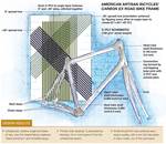
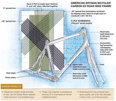
“My first exposure to the concept which later became C-PLY was as a student in Dr. Stephen Tsai’s ‘Composite Design Workshop’ offered by Stanford [University],” says Skillen. “The approach made a lot of sense,” he recalls. “Rather than try to make laminates that approximate isotropic materials, C-PLY is designed around the fiber properties and ply orientations (angles) that enhance laminate performance.” (See "Bi-angle fabrics find their first commerical application," under “Editor's Picks,” at top right.)
C-PLY combines several positive traits: It is a noncrimp fabric (NCF), it features anisotropic biaxial construction, and its fibers are oriented at a low angle — it is sometimes described as “bi-angle” due to its 0°/θ° construction, where a low value of θ, e.g., 20° to 30°, reduces interlaminar stress, enhancing load transfer between plies without matrix cracking. Further, its spread-tow construction makes it remarkably thin.
Although quasi-isotropic symmetric lay-ups (traditional “black aluminum”)are commonly used in composites because they mimic the properties of the metals they replace, computer-based analytical tools enable detailed ply-by-ply analysis, allowing designers to exploit the benefits of low-angle anisotropic design. The end result is better properties for the same weight or as much as 40 percent less weight than an aluminum structure for similar performance.
The use of a larger number of very thin plies reduces interlaminar stress and enhances toughness. “Like in a beetle shell, an optimized composite theoretically would have layers just a few fibers thick,” explains Skillen. C-PLY uses 12K, 24K, 48K or 50K tow, spread very thin but without gaps. The 12K spread tows VX Aerospace has used so far (0.003-inch/0.076-mm ply thickness) are much thinner than most unidirectional (UD) prepregs and weigh in at only 75 g/m2 (2.2 oz/yd2).
VX Aero expects to have a steady source for the new material. Chomarat is installing a production line (scheduled to be operational by mid-year 2014) capable of producing any stitched multiaxial configuration, but optimized to produce 100-inch/2.5m wide NCF with angles from 30° to 90°. Multiaxials with angles of less than 30° are available in a reduced width. Skillen emphasizes that the stitched two-ply fabric VX Aerospace has been using — totaling 0.006-inch (0.152-mm) thickness and 150-g/m2 (4.4-oz/yd2) weight per layer — is tailored for structural loads but is far easier to place and much less equipment-intensive than automated tape placement.
Currently, two composite aircraft projects occupy the company’s 17,000-ft2 (1,579m2) production space. Both will make extensive use of C-PLY. The first is the Falcon, a sleek, low-wing, high-performance sport aircraft esteemed by some as “the Ferrari of light aircraft.” Originally built in Hungary, a handful of the planes made it to the U.S. before the manufacturer, Corvus, went bankrupt. A groundswell of demand spurred an effort to put the plane into production in the U.S. Via a memorandum of understanding with Renegade Light Sport Aircraft (Deland, Fla.), VX has assumed responsibility for design, engineering, tooling and manufacture of the Falcon airframe, while Renegade controls sales, marketing and FAA certification.
The other aircraft is a 1:4 scale version of the VX Aerospace-designed VX-1 KittyHawk. Its unique blended wing/fuselage is designed to exploit aerodynamics and potential alternative fuels to cut flight cost per mile by a factor of three while offering more internal volume and payload. Like its Wright Brothers namesake, the KittyHawk is poised to score a first of its own: It will be the first aircraft to fly with C-PLY laminates.
Skillen believes that the new material combined with OOA processing can enable small composite airframers the opportunity to produce structures with the same precision and performance as those fabricated by big aerospace OEMs and primes, but at a fraction of the latter’s delivery time and cost.
Designed for manufacturability
The single-engine Falcon is 21 ft/6.4m long, with a 31.5-ft/9.6m wingspan. It can cruise at 140 mph (225 kph), burning less than 5 gal/18.9 liters of fuel per hour. For the North American market, VX Aero is maintaining the plane’s look and basic dimensions but also taking steps to improve its structural design.
Because the plane’s defunct creator’s design data were unavailable, development began with white-light 3-D digital scanning of the entire aircraft (using a structured-light scanner rather than a laser scanner) from which it developed CAD surface models. Then came the critique: “Original production was most likely using hand-built masters and tooling,” says Skillen. The fuselage had a significant amount of asymmetry. There were butt-jointed cored panels without any means for load transfer and a lack of hard points for structural connections. The construction scheme needed improvement, and it would be necessary to optimize the design for manufacturability. “Quality and efficiency had to be designed into every assembly and process,” he says, “to control costs and cycle time in an actual production environment.”
In pursuit of those goals, VX Aero is employing the concept of ‘self-rigging subassemblies’ in the Falcon’s design. For example, the heart of the airframe is a carbon fiber-reinforced plastic (CFRP) spar box. As the anchor component of the wingbox assembly (see photo at left), its outer mold line (OML) surfaces align with and locate those of the next higher assembly. This helps to minimize the cost and complexity of assembly fixtures yet hold tight tolerances.
The new wingbox assembly also addresses an issue in the original aircraft. Namely, landing gear loads were directly imparted to the fuselage with no load path carry-through from one side to the other. And because the large fuselage cutout for the polycarbonate cockpit canopy is located directly above the region that absorbs gear loads, this structural configuration resulted in unacceptable deflection. To compensate, VX Aero redesigned the forward and aft seat beams as key elements of the wingbox assembly. They are now attached through the wing roots to the spar box, which now provides the primary load path for the wing moments.
Materials and assembly
The spar box is a continuous box beam with 0.1-inch/2.5-mm thick walls. Both its A and B (inner and outer) sides are critical dimensions. The outside locates the fore and aft gussets — they add stiffness and supplementary paths for landing gear loads — while the wing spars must fit inside the spar box ends. A 3-D fabric, woven from T700 carbon fiber supplied by Toray Industries, was chosen to handle the structure’s high interlaminar shear loads. Supplied in the form of a sock-like preform by Highland Industries, a subsidiary of technical textile source Takata (Tokyo, Japan), it enables quick lay up of 10 plies over an expandable mandrel.
Notably, VX Aero has replaced the sandwich construction of the original craft, which featured extensive use of foam and honeycomb core, with monolithic skins reinforced by post-bonded hat stiffeners to reduce weight and enhance manufacturability. The canopy cutout is now bolstered by a CFRP rail that Skillen integrated into the glare shield as a one-piece structure. Thus, a reliably consistent fuselage/canopy interface is achieved with minimal parts and assembly. “The canopies will fit easily into the fuselage opening every time and be interchangeable with each other in the field,” Skillen explains.
Once the wingbox assembly is complete, fixed inner cockpit panels will be attached to the forward and aft seat beams and then the rail/glare shield will be affixed, followed by the cabin floor and firewall, which separates the engine from the cabin. Finally, the fuselage halves will be bonded using a fixture designed to account even for the glue thickness tolerances.
After the firewall and fuselage are bonded, the aircraft’s engine, still connected to its wheeled stand, is bolted to the firewall. Because the Falcon fuselage will only weigh 70 lb/154 kg, the assembly can be wheeled around the production floor easily, eliminating the need for a crane.
The wingbox assembly is all CFRP: 3-D woven material in the spar box and 3K plain weave in the other components. Like the original, the new Falcon will use glass fiber prepreg in the fuselage. Glass reinforcement is sufficient because the fuselage loads are smaller than those in the wing, and glass reinforcement will enable the radio transmissivity of internal antennae.
Prepreg layup, rather than what would be a complex infusion setup, was chosen for the fuselage, based on manufacturability and consistency/repeatability. Prepregged C-PLY will be used in the wing spars, wing skins and horizontal tail. Most of the other small parts will be infused, but some will be made using wet layup. Each material and process has been chosen with the balance between part performance and manufacturing efficiency in mind.
Fast Falcon retooled
After 18 months of computer modeling every component on the airplane, CAD files were fed to VX Aero’s 3-axis CNC machining unit by Diversified Machine Systems (DMS, Colorado Springs, Colo.), which cut precision masters (top photo, p. 58) from 38-lb/ft3 (0.6-g/cm3) RAKU-TOOL plastic board supplied by Rampf Tooling (Grafenberg, Germany). Pattern surfaces were prepped and sealed with Chemlease (Chem-Trend, Howell, Mich.) and then polished and coated with Chemlease again in preparation for laminate lay up (bottom photo, p. 58).
VX Aero uses recycled carbon fiber mat (photo, p. 58) from Materials Innovation Technology Recycled Carbon Fiber (MIT RCF, Fletcher, N.C.) as the tooling bulk layers to build thickness quickly and cheaply (less than $2.00/ft2), interspersed with 3K carbon fiber plain weave fabric (about $5.00/ft2). This dry laminate is then infused with 350°F/180°C-cure PT5712 epoxy tooling resin from PTM&W Industries Inc. (Santa Fe Springs, Calif.), postcured at 25°F over Tg for 18 hours and then surface coated. The Falcon’s fuselage tools were made using LTM318-1B glass fiber/epoxy OOA tooling prepreg from Cytec Aerospace Materials (Tempe, Ariz.) to match the final part materials.
“Everybody loves vinyl ester surface coats because they are hard, not prone to air leaks and have less water ingression,” notes Skillen, “But they are not compatible with epoxy matrix resins.” VX Aerospace achieves a vinyl ester (VE) surface coat by using 1799-006 vinyl ester primer from Hawkeye Industries Inc. (Bloomington, Calif.). Skillen says the resulting tools are void-free with very high gloss surfaces (see photo, at left).
By the end of 2013, VX Aerospace had completed masters for the Falcon’s horizontal tail and all of the fuselage components. Tooling from those masters is close to completion. The wing tooling is next in line. Limited rate production of 20 aircraft per year is planned using a team of 20 employees.
First in flight
The VX-1KittyHawk strikes a marked contrast with the Falcon. Its blended wing body features wings that are smoothly blended into an airfoil-shaped fuselage, achieving a 50 percent greater lift-to-drag ratio than conventional designs. Skillen points out that the most efficient airfoil is elliptical, like a Spitfire. “This is exactly the top profile of the KittyHawk,” he adds.
At full scale, the plane will measure 26 ft/8m in length with a span of 22.5 ft/7m and a body height of 4 ft/1.25m, offering significantly more usable internal volume than other aircraft of similar gross weight. (Empty weight will be ~750 lb/340 kg, using 100- to 125-hp engines). “It will offer a 7-ft/2m cockpit width, which is unique in this size aircraft.” As a UAV, its larger internal volume permits more payload and sensors. In the manned light aircraft market, it means more cockpit comfort, and greater cargo and fuel capacity. There are also no wings to break off upon landing, improving aircraft recovery for UAVs, and it offers the option to be powered by compressed natural gas (see “A UAV fueled by CNG?” sidebar, at the end of this article or click on its title under "Editor's Picks").
With support from North Carolina State University (NCSU, Raleigh, N.C.), computational fluid dynamics (CFD) analysis and wind tunnel testing were completed in October and November 2013, managed by Dr. Richard D. Gould, chair of the Mechanical Engineering and Aerospace Department. According to Skillen, results have exceeded expectations. The aircraft generates 20 lb/44 kg of lift at 0° angle of attack (i.e., no tilt relative to the airflow direction), which equates to 100 ft/sec (31 m/sec) at 68 mph/109 kph. In other words, the aircraft generates lift quickly without requiring a lot of speed to take off. “That’s almost twice as aerodynamically efficient as most other light aircraft,” says Skillen. It also demonstrates good dynamic stability (ability to recover after disturbance from normal flight), and no further modifications will be needed prior to flight testing. NCSU will help here as well, says Skillen, by flying the 1:4 scale aircraft with a telemetry package to map out all of its flight characteristics and, thus, verify the CFD analysis.
Prototype to production
“We are applying modern CFRP technology to make the traditional performance of blended wing body aircraft even better,” says Skillen. The aircraft’s structurally efficient shape eliminates the need for high-strength spars. Thus, the airframe is essentially hollow. Beyond its top skin, bottom skin and four ribs that make up the body, the only other parts required are vertical fins and flight control surfaces. Skillen asserts that this makes the KittyHawk easy and cost-effective to manufacture.
Such a design, however, requires large, unsupported, high stiffness-to-weight structural panels. “This is the sweet spot for CFRP construction,” Skillen claims, noting that, here, “C-PLY furthers the weight savings possible, with skins that are significantly lighter than if using 3K plain-weave fabric.” He adds that C-PLY speeds the layup, with two plies applied at once, and results in laminates with a more homogeneous fiber distribution throughout, which increases fracture toughness compared to conventional unidirectional materials.
Tooling for the 1:4 scale aircraft was directly CNC-machined from plastic tooling board because it is temporary and, therefore, can be designed for short life and low cost. Layup of the 1:4 scale aircraft structures used six layers (12 plies total) of C-PLY, again with a 150-g/m2 weight and 0.006-inch thickness per two-ply layer. Parts were then infused using PTM&W’s 2712 epoxy resin. Demolded parts were then assembled. First, ribs were bonded to the bottom skin; then the top skin — which includes openings for payload access — was bonded to this assembly. The payload access cover was then attached with mechanical fasteners.
The first finished airframe was displayed by Chomarat at JEC 2014 (March 11-13, Paris, France). A second 1:4 scale aircraft, assembled in March, was delivered to NCSU for flight testing.
Skillen anticipates full-scale aircraft production will likely use C-PLY prepregged with Cytec’s Cycom MTM45-1 OOA prepreg resin. However, the final decision, prepreg vs. infusion, will be made based on the customer’s production volume. (Several potential customers, are awaiting flight test results before making commitments.) Parts can be layed up quickly using C-PLY.
Skillen estimates the VX-1 KittyHawk will use 6,000 ft2/557m2 of C-PLY per plane. “We could design and make this aircraft with traditional carbon fiber roll goods,” Skillen admits, “but the efficiency and performance C-PLY delivers gives a small company like us a real competitive advantage.”
Related Content
Plant tour: Joby Aviation, Marina, Calif., U.S.
As the advanced air mobility market begins to take shape, market leader Joby Aviation works to industrialize composites manufacturing for its first-generation, composites-intensive, all-electric air taxi.
Read MorePlant tour: Albany Engineered Composites, Rochester, N.H., U.S.
Efficient, high-quality, well-controlled composites manufacturing at volume is the mantra for this 3D weaving specialist.
Read MoreCryo-compressed hydrogen, the best solution for storage and refueling stations?
Cryomotive’s CRYOGAS solution claims the highest storage density, lowest refueling cost and widest operating range without H2 losses while using one-fifth the carbon fiber required in compressed gas tanks.
Read MoreCarbon fiber, bionic design achieve peak performance in race-ready production vehicle
Porsche worked with Action Composites to design and manufacture an innovative carbon fiber safety cage option to lightweight one of its series race vehicles, built in a one-shot compression molding process.
Read MoreRead Next
Bi-angle fabrics find first commercial application
Bicycle manufacturer sees dramatic productivity gains using unbalanced fabrics conceived at Stanford University and manufactured by Chomarat.
Read MoreDeveloping bonded composite repair for ships, offshore units
Bureau Veritas and industry partners issue guidelines and pave the way for certification via StrengthBond Offshore project.
Read More


