What’s the most important type of mechanical test for composites?
When the opportunity arises, I like to ask those familiar with composites testing this question: What type of mechanical test do they consider to be the most important for composite materials?
When the opportunity arises, I like to ask those familiar with composites testing this question: What type of mechanical test do they consider to be the most important for composite materials? After listening to responses, I follow up by asking people what they think is the primary purpose for performing the test and what are its intended applications. I’ll share here what I’ve learned from asking these questions. But before I do, I’d suggest those who read this spend a minute thinking about what their responses would be to these questions.
Perhaps it comes as no surprise that there is no single type of mechanical test that’s the consensus choice as most important for composites, especially given the variety of purposes for testing and intended applications. There are, however, a few test methods that were more often mentioned. These can be grouped into three general categories and best discussed in terms of the primary purposes for performing the test.
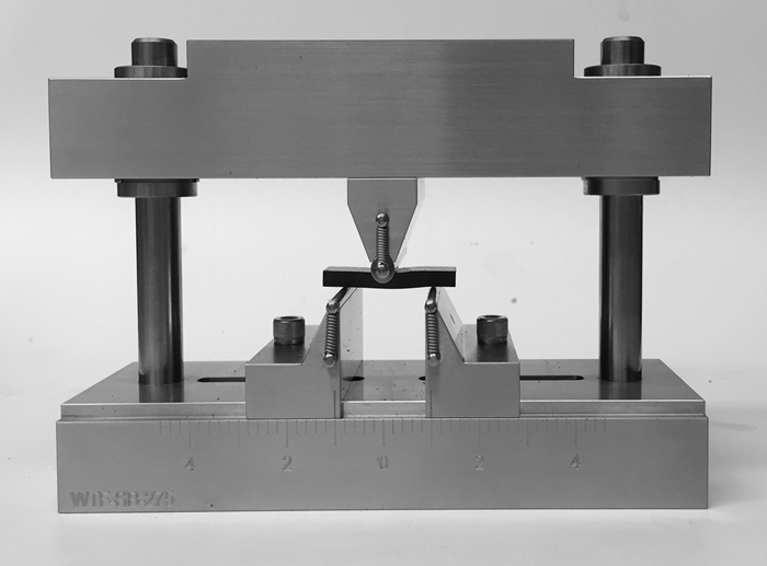
One test method mentioned frequently as most important is the short beam shear test, described in ASTM D 23441 (Fig. 1). One of the simplest to perform, it uses the smallest test specimen of any mechanical test method for composites. The test consists of a three-point bend test performed using a short loading span relative to the specimen thickness. This results in interlaminar shear failure within the specimen’s interior. The measured short beam strength is highly sensitive to problems with porosity, fiber-to-matrix adhesion and the layer-to-layer strength within the composite laminate. Therefore, although the measured short beam strength may be considered only an estimate of the interlaminar shear strength, this test method is widely considered an excellent choice for comparative testing purposes. Accordingly, stated purposes for performing this test include material comparison and selection, material and fabrication process development and quality control.
Not as commonly mentioned as most important, the ±45° tensile shear test, ASTM D 35182, may be used for these purposes as well. The advantage of this test is that it produces a shear stress vs. shear strain curve throughout the loading and, thus, provides a measurement of shear modulus in addition to shear strength. The nonlinear shear stress vs. shear strain curve is analogous to a “fingerprint” that corresponds to a tested material, allowing for a more thorough comparative assessment between materials or processing conditions. However, the disadvantage is the required use of bonded strain gages for shear strain measurement and, therefore, significantly greater effort and cost. As a result, the ±45° tensile shear test remains a distant second choice as most favorite for the above stated purposes.
Another common purpose for performing mechanical testing of composites is to determine material properties for use in design and analysis. While many types of material characterization tests are performed with composites, compression strength testing in the fiber direction is often considered most important. The reason? For virtually all carbon fiber-reinforced polymer matrix composites, the compression strength is significantly lower than the tensile strength and, therefore, is the limiting design value. Interestingly, those who identify compression testing as most important sometimes will also identify the most important test environment in which to perform the test. For polymer matrix composites, the most severe environmental condition is often the highest service temperature, coupled with a moisture saturation condition. This “hot/wet” combination is typically specified as the most important environmental condition in which to perform the fiber-direction compression test.
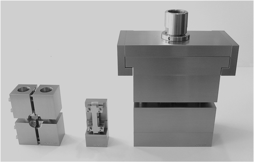
In my July 2015 column, I discussed the variety of test methods available for determining the compression strength of composites. The primary way in which they differ is the method of load introduction into the specimen. The three most commonly performed tests (Fig. 2) are the combined-loaded ASTM D 66413 test, the end-loaded, Boeing-modified D 6954 test and the face-loaded ASTM D 34105 test.
The final category of test methods that have received a considerable number of most important votes are those used to develop structural design allowables. For this purpose, the open-hole compression test, ASTM D 64846, and the compression-after-impact test, ASTM D 71377, have been named most important, particularly for aerospace applications.
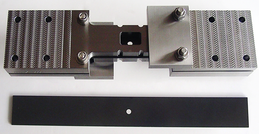
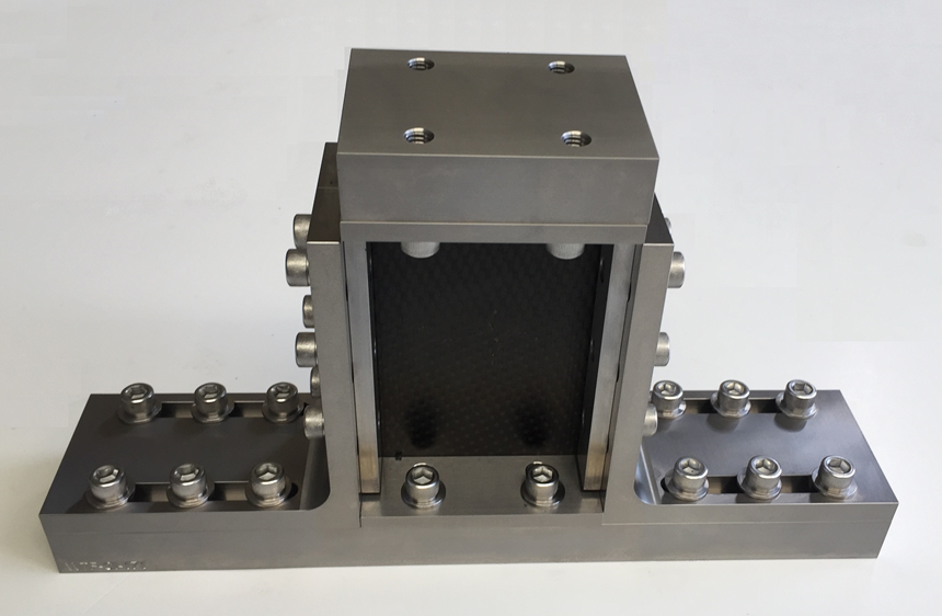
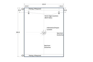
The open-hole compression test (Fig. 3a) uses a 36-mm-wide specimen with a central 6-mm-diameter hole, producing a specimen width-to-hole diameter (w/D) ratio of 6:1. To prevent buckling during compression loading, a support fixture is bolted to the 300-mm-long specimen. The ASTM D 7137 compression-after-impact test uses a 100-mm-wide by 150-mm-long specimen that is loaded in edgewise compression while it is supported to prevent out-of-plane bending along the vertical edges (Fig. 3b). Prior to compression testing, the specimen is subjected to a drop-weight impact to produce damage in the specimen’s central region. Note that when structural design allowables are generated using either test method, the composite laminate used in the test specimen is representative of the laminate that will be used in the intended application. For compression-after-impact testing, the impactor shape and impact energy used to produce the damage are also selected to represent impact threats for the application of interest.
In addition to producing critical structural design allowables for a variety of applications, these two test methods share other important features. First, both are performed under compression loading because the resulting strengths typically are lower than those under tension loading. Second, both tests produce design allowables that typically are more critical than those resulting from the strength-based material properties discussed in the previous category. As a result, both the open-hole-compression and compression-after-impact tests also are commonly used in the material selection process for an intended application. Because a consistent laminate must be used when testing to compare candidate materials, the use of a quasi-isotropic laminate is suggested.
REFERENCES
1ASTM D 2344/D 2344 M-16, “Standard Test Method for Short-Beam Strength of Polymer Matrix Composite Materials and Their Laminates,” ASTM International (W. Conshohocken, PA, US), 2016 (first issued in 1965).
2ASTM D 3518/D 3518 M-13, “Standard Test Method for In-Plane Shear Response of Polymer Matrix Composite Materials by Tensile Test of a ±45° Laminate,” ASTM International (W. Conshohocken, PA, US), 2013 (first issued in 1994).
3ASTM D 6641/D 6641 M-16, “Standard Test Method for Compressive Properties of Polymer Matrix Composite Materials Using a Combined Loading Compression (CLC) Test Fixture,” ASTM International (W. Conshohocken, PA,US), 2016 (first issued in 2001).
4Modified ASTM D 695 Compression Test Fixture, Wyoming Test Fixtures Inc., http://www.wyomingtestfixtures.com/Products/b2.html.
5ASTM D 3410/D 3410 M-16, “Standard Test Method for Compressive Properties of Polymer Matrix Composite Materials with Unsupported Gage Section by Shear Loading,” ASTM International (W. Conshohocken, PA, US), 2016 (first issued in 1975).
6ASTM D 6484/D 6484 M-14, “Open-Hole Compressive Strength of Polymer Matrix Composite Laminates,” ASTM International (W. Conshohocken, PA, US), 2014 (first issued in 1999).
7ASTM D 7137/D 7137 M-17, “Compressive Residual Strength Properties of Damaged Polymer Matrix Composite Plates,” ASTM International (W. Conshohocken, PA.), 2017 (originally published 2005).
Related Content
Photothermal tomography for locating, quantifying defects in composites
Years of infrared testing development result in thermography technology that is no longer just qualitative, but can define defect size and depth, making additional UT scans obsolete.
Read MoreCrashworthiness testing of composites: A building block approach, Part 1
Determining the crashworthiness of composite structures requires several levels of testing and analysis, starting with coupon-level crush testing.
Read MoreDamage tolerance testing of sandwich composites: The sandwich CAI test
A new ASTM-standardized test method established in 2022 assesses the compression-loaded damage tolerance of sandwich composites.
Read MoreCrashworthiness testing of composites: A building block approach, Part 2
Following the previously discussed coupon-level testing element, subcomponent and component testing are the next steps in designing crashworthy composite structures.
Read MoreRead Next
“Structured air” TPS safeguards composite structures
Powered by an 85% air/15% pure polyimide aerogel, Blueshift’s novel material system protects structures during transient thermal events from -200°C to beyond 2400°C for rockets, battery boxes and more.
Read MoreDeveloping bonded composite repair for ships, offshore units
Bureau Veritas and industry partners issue guidelines and pave the way for certification via StrengthBond Offshore project.
Read MoreAll-recycled, needle-punched nonwoven CFRP slashes carbon footprint of Formula 2 seat
Dallara and Tenowo collaborate to produce a race-ready Formula 2 seat using recycled carbon fiber, reducing CO2 emissions by 97.5% compared to virgin materials.
Read More

