Share
Read Next
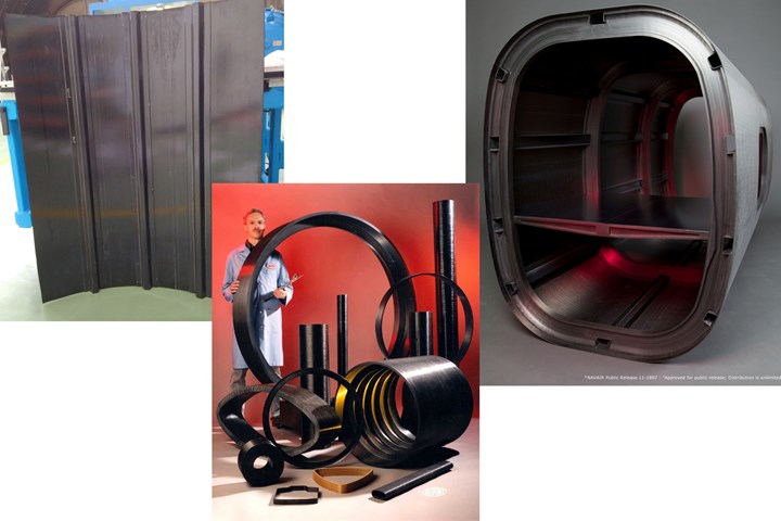
In-situ consolidated thermoplastic composite parts by (left to right) FIDAMC, Accudyne Systems and Automated Dynamics, now Trelleborg, TSS Albany. Photo Credit: FIDAMC, Accudyne Systems, TSS Albany
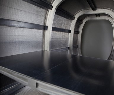
Image at top, in-situ consolidated thermoplastic composite tail boom structure by TSS Albany. Photo Credit: TSS Albany
For more than six decades, composites have earned their way onto commercial aircraft, literally step by step. At each stage, they’ve proven themselves capable of forming increasingly flight-critical parts with the required strength, stiffness and near absence of flaws — surface porosity and unseen internal voids — that could be the source of future damage as aircraft age. Until comparatively recently, that near void-free standard (<1% porosity) was maintained by a combination of vacuum bag consolidation and, typically, many hours of exposure to high heat and pressure in an autoclave during the curing process. In recent years, development of oven-curable resins (systems that can be consolidated to acceptable void contents without an autoclave) have helped to shorten cure cycles and, because ovens cost less to operate than autoclaves, to reduce both the time and expense required to produce parts. In parallel, automated filament winding, automated tape laying (ATL) and automated fiber placement (AFP) equipment have replaced hand layup in many applications, radically increasing the speed at which parts can be laminated. Although these systems are equipped with rollers that compress the material immediately after placement to ensure adhesion and avoid formation of air pockets that would create voids, consolidation of the laminate still typically occurs in the second step of what remains a two-step process, under a vacuum bag, in an autoclave, oven or other heating device, such as a heated tool. This state of the art persists, at least in part, because today’s certified aerocomposite materials are predominately thermoset-based.
There is an alternative. In fact, there has been one for decades. Known as in-situ consolidation, it means, consolidation in place. The key is the use of thermoplastic rather than thermoset matrices. Thermoplastic materials are liquid when heated to melt temperature and solidify when cooled, but do not need to crosslink like thermosets. Consolidation of a thermoplastic composite (TPC), then, can be accomplished by quickly heating the impregnated reinforcement to the melt temperature of the thermoplastic polymer matrix and then applying pressure as the tape or tows are placed onto a tool and/or a previously placed laminate. True in-situ consolidation (ISC) is a one-step process — no further heating or pressure steps are required after fiber placement or tape laying is completed.
The implications of eliminating an entire and expensive step in the manufacturing process are so significant and obvious that one might ask, why isn’t everyone already doing it? For one (there are other reasons, to be discussed), the aerospace industry pays a very steep price for change. Materials substitutions inevitably require extensive and costly testing and recertification.
Two-step consolidated thermoplastic composites are an alternative to in-situ consolidation, shown here via an aeroengine pylon structure made by NLR (left) and a stringer-stiffened torsion box components for an aircraft tail by GKN Fokker (right). Photo Credit: NLR, GKN Fokker
That said, two-step consolidated TPCs are already in use in select aircraft applications. Although their processing temperatures are much higher than thermosets — closer to 400°C vs. 180°C/350°F for primary structures — their cycle times are much shorter because TPCs require only cooling rather than crosslinking. Thermoplastics also are inherently tough, and need no special formulation to provide the fatigue-resistance necessary for aircraft applications. Further, because thermoplastics can be reheated and reformed, they can be welded (a cost-saving, fastener-free assembly option). As the aircraft industry pursues materials and processing options that will enable production rates of at least 60 aircraft/month and support the envisioned digital manufacturing, multifunctional structures and sustainability that are deemed necessary for next-generation aircraft, TPCs have emerged as frontrunners. In an impressive percentage of recently completed, large-scale aircraft demonstration projects, TPCs have been the material of choice.
In this first of a two-part series, CW explores the history of ISC TPC structures, memorializing the almost four decades of development that has laid the foundation for this one-step technology.
In-situ early on
Development of TPC aerostructures began in the 1980s in The Netherlands. Fokker Aerostructures (Hoogeveen) and Fokker Technologies (Papendrecht) — both now part of GKN Aerospace (Redditch, UK) — started work with materials supplier TenCate, now Toray Advanced Composites (TAC, Nijverdal, Netherlands) that “resulted in the J-nose for the A330/A340 and then the A380,” recalls Henri de Vries, senior scientist, composites, in the Structures Technology Department at the Netherlands Aerospace Centre (NLR, Amsterdam). A research institute that supports the Dutch aerospace industry, the NLR began working with Fokker and TenCate/TAC, and is now touted as one of the aviation industry’s great reservoirs of TPC knowledge.
“In 1986, we had a high-temp autoclave, Fokker had facilities for press forming and resistance welding, and TenCate had the ability to make flat panels,” de Vries continues. Glass fiber/PPS J-nose technology was developed using press-molded ribs and an autoclave-cured skin. Though these were not ISC structures, they were the first TPC structures to fly and pioneered the use of resistance welding, a process that de Vries says, “was unique at the time.” (Learn more about Fokker’s production of thermoplastic J-nose structures in CW’s Plant Tour titled, “Fokker Aerostructures: Hoogeveen, The Netherlands.”)
Across the Atlantic, Automated Dynamics (Niskayuna, NY, US, now part of Trelleborg Group, Trelleborg, Sweden), began its first TPC project in 1985-86. “It was an SBIR [small business innovation research grant] funded by the US Army for development of a helicopter main rotor blade spar,” says Automated Dynamics president Robert Langone. “In-situ consolidation was a focus from the beginning.” A hot nitrogen gas torch was used to heat the thermoplastic to its melt temperature. A few years later, the company developed a heated roller for compaction. Quality further advanced when it acquired personnel and technology from Imperial Chemical Industries (ICI) Composites, the original developer of Victrex (Cleveleys, Lancashire, U.K.) polyetheretherketone (PEEK), also known as APC-2 in its unidirectional (UD) tape prepreg form, a material still in use today.
“We were founded to sell machinery, but by the early 1990s we were producing in-situ consolidated cylindrical parts every day,” notes Langone. Automated Dynamics sold its first articulated arm-based ISC workcell to NASA Langley Research Center (Hampton, VA, US) in 1994, and by the late 1990s was fully immersed in industrial production of ISC parts for the oil and gas industry. These included antenna shields, logging sleeves, plugs, pipes, pressure vessels and more, made from glass, aramid and/or carbon fiber (CF) and a range of matrix materials, including PEEK, polyethylene (PE), polypropylene (PP) and others.
De Vries notes that Accudyne Systems Inc. (Newark, DE, US) also was an ISC pioneer, “the first to characterize the process window and develop a flexible compression head to keep pressure on the material as it cools.” That was important because PEEK, polyetherketoneketone (PEKK) and PPS, as semi-crystalline polymers, develop the crystalline lattice structure, which imparts their notable mechanical properties and chemical resistance, as they cool. Like Automated Dynamics, Accudyne’s first work relied on hot gas torches and heated shoes.
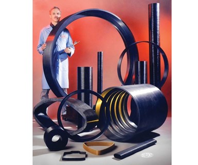
Accudyne achieved autoclave-level properties in CF/PEEK cylinders, the largest (shown here) at 152 cm in diameter. Photo Credit: Accudyne Systems Inc.
“One could almost say that Accudyne’s work around in-situ consolidated TP parts began with DuPont,” says Mike Smoot, VP sales and marketing at Accudyne Systems. Several Accudyne employees were part of DuPont’s Advanced Materials Group in the 1980s and ’90s. “During that time,” he continues, “we developed a thermoplastic head and placed it on a standard filament winder. Infrared [IR] lamps heated the incoming tow, hot shoes guided the material onto the part, hot gas torches heated the laydown area and chilled pressure rollers cooled the molten polymer. Noncontact IR sensors measured the temperature of the incoming tow and laydown area, adjusting the thermal devices accordingly to stay within the required PEEK or PEKK process specifications.”
DuPont’s work led to its participation in an early 1990s Defense Advanced Research Projects Agency (DARPA) program to build a 610-mm (24-inch) diameter, 16-mm (0.629-inch) thick ring-stiffened cylinder, using IM7 carbon fiber/APC-2 UD tape. Smoot says the ISC cylinder achieved <1% porosity and failed within 3% of its design load when tested underwater at 5,500 psi. This success opened other development opportunities for a variety of parts including rings and bearings for chemical processing, sonar shells, handheld rocket launch tubes, helicopter pitch links, and containment rings for high-speed permanent magnet rotors.
From 1998 to 2012, Accudyne did extensive work in developing an in-situ laminator that could process either 76-mm (3-inch) wide tape or 12 ends of 6.35-mm (0.25-inch) tow. Initial effort focused on simple flat panels but ultimately resulted in a conformable head capable of producing panels with mild curvature, pad-ups, drop offs, titanium honeycomb core and TPC stiffeners.
“These were gantry-based systems that used hot shoes, hot rollers, IR lamps, gas torches and chilled rollers to process the thermoplastic tapes with automated placement onto a 1m-by-1m rotary table,” says Smoot. “Accudyne produced a similar rotatory table for Fiberforge’s first RELAY machine, placing tape at whatever angle was necessary.” Now-defunct Fiberforge (Glenwood Springs, CO, US) sold its RELAY technology to Dieffenbacher (Eppingen, Germany). Accudyne used the in-situ laminator to make hundreds of panels and characterized the laminates via open hole compression (OHC), short beam shear (SBS) and many other tests, achieving 89-95% of autoclaved composite properties. “The head could in-situ laminate CF/PEEK panels at 3.05 m/min with voids less than 2%,” notes Smoot, “but it was difficult to get below 1% voids, partly due to the incoming materials having void contents as high as 20% and a rough surface, which limited the intimate contact of the mating plies.”
Advancing consolidation for aerostructures
By the early 2000s, Fokker, TenCate and NLR had amassed significant experience with thermoplastic structures fabrication and KVE Composites Group (Den Haag, The Netherlands) had pioneered induction and resistance welding. NLR not only had characterized a wide range of thermoplastics, from polyamide (PA) to polyetherimide (PEI), PPS, PEEK and PEKK, but also had researched the effect of crystallinity on mechanical properties and focused on automated processing, including welding and ISC technology.
“We began with an Automated Dynamics gas torch-heated machine but later replaced that with a Coriolis system because we saw the benefits of laser heating and also the potential to use infrared heating in a single machine,” de Vries explains. Coriolis Composites (Quéven, France) began producing AFP systems in 2000. “From the beginning, all of our machines have been developed to handle thermoplastic, thermoset or dry fiber materials,” says Coriolis chief technology officer and director Alexandre Hamlyn.
NLR’s more in-depth work on ISC included how to compress the material, “and how to do this on doubly curved surfaces, which is quite complicated,” he adds. “We also looked at laser optics. We developed a computer model to look at the laser heating process starting from the creel up to full consolidation of the laid material. We worked with Coriolis to refine this process and the equipment.” The heating cycle is complex, notes de Vries, “because you must process fast without burning the material.”
“Airbus has really been the major force developing in-situ consolidated thermoplastics technology,” Hamlyn points out. “It has many competitive projects in France, Spain, Germany and the UK, and is also working with the NLR in The Netherlands.” However, Airbus R&D in automated laying of TPC materials began in France, led by the company’s chief technology office (CTO) in Suresnes. “We worked with Coriolis to develop robotic AFP into an industrial solution with the FlashTP machine,” recalls Cyrille Collart, Airbus head of (HO) Innovation & Development, Manufacturing Technologies Composites (Nantes, France). He notes the Flash TP machine is still used in Airbus TPC developments, installed at the Technocampus EMC2, a research and technology transfer center located adjacent to Cetim and the Airbus production facility in Nantes. (Learn more about Cetim’s TPC technologies in the CW Blog titled, “Automated Preforming — Quilted Stratum Process (QSP)”.)
Pursuing large, primary structures
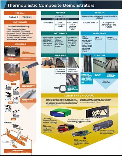
There is a TPC development roadmap in Europe, supported by Airbus and a variety of national aerospace consortia — e.g., TAPAS1, TAPAS2 in The Netherlands and the Civil Aviation Research Council (CORAC) “Investing in the Future” program in France — plus programs in Germany, Austria and Spain. (Read more about the TAPAS programs “Thermoplastic composites: Primary structure?” and “TAPAS 2: Next steps in thermoplastic aerostructures.”) These programs are coordinated with, and feed into, much larger pan-European collaborations, notably Clean Sky (2008-2016) and Clean Sky 2 (2017-2021), which are part of the European Commission’s Horizon 2020 program (2014-2021). Note these are public/private partnership (PPP) programs deliberately organized to achieve technology readiness level (TRL) 6 for multiple composites and metals technologies and eventual downselection for future aircraft production. They also involve almost every major aerostructures supplier in Europe.
Having demonstrated co-consolidated TPC skin-stringer structures in increasingly larger sizes and complexity, these programs are now ramping to full-scale fuselage demonstrators in Clean Sky 2. The Multifunctional Fuselage Demonstrator is particularly interesting, featuring an asymmetrical, half-barrel fuselage design that will be manufactured by 2020 using thermoplastic composites. The goal is to integrate cabin, cargo and aircraft systems with the airframe to reduce weight and manufacturing cost while enhancing space for passengers and cargo.
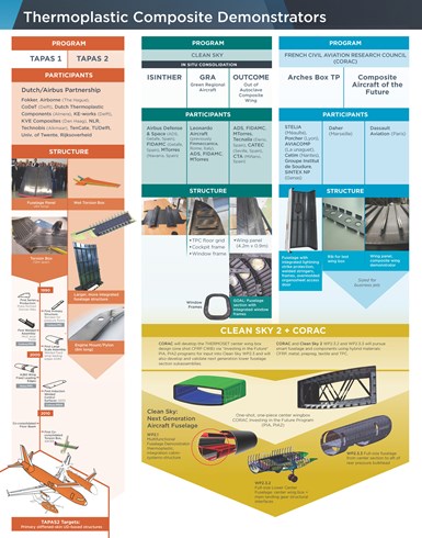
Roadmap of thermoplastic composite developments in Europe as of 2018. Photo Credit: Airbus, Clean Sky 2, Daher, FIDAMC, GKN Fokker, Stelia, CW.
In general, TPC development in France and The Netherlands has pursued a two-step approach while one-step ISC has been favored in Spain. Full details about these programs, program participants and outcomes can be read in the Side Story titled, “Thermoplastic composite demonstrators — EU roadmap for future airframes.”
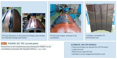
INSCAPE — In-situ manufactured carbon/thermoplastic curved stiffened panel — continues development by Airbus DS (Defense and Space, Madrid, Spain) with FIDAMC from Clean Sky 1, and will feed into the Clean Sky 2 Airframe Integrated Technology Demonstrator (ITD). “The curved structure that was proposed by Airbus DS tries to demonstrate manufacturing capabilities dealing with curvature and tapering on stiffened panels,” explains Rene Adam, R&D director at program partner and composite aerostructures supplier FACC (Ried im Innkreis, Austria). He notes that INSCAPE’s approach is similar to FIDAMC’s in terms of stringer-skin installation and a one-step AFP in-situ consolidation process with laser heating (Fig. 2). “It complements FIDAMC’s gantry-installed AFP for semi-flat wing panels in the OUTCOME project,” says Adam. “INSCAPE addresses higher curvatures and tapering with a more flexible Kuka robot arm and a different manufacturing process for stringers, as well as different material suppliers and faster layup speeds.” He adds that this type of structure may be used in engine nacelles, fuselage doors or the tail cone section of the fuselage, and also in higher curvature structures, such as leading edges, pylons, flaps or other movables.
STELIA Aerospace (Toulouse, France) exhibited a TPC fuselage demonstrator at the 2017 Paris Air Show that features welded stringers and frames as well as lightning strike protection (LSP) integrated into the skin during AFP (Learn more about STELIA’s Arches Box TP demonstrator in the stories “STELIA Aerospace develops induction welding technology” and “Porcher works with Stelia Aerospace on thermoplastic fuselage.” Also watch this video.)
Automated Dynamics developed the full-size, integrally stiffened, in-situ consolidated thermoplastic helicopter fuselage pictured at top in 2012, after many sub-scale demonstrators in the prior decade. Photo Credit: Automated Dynamics
Automated Dynamics also has patented LSP integrated during AFP, but the full-size, integrally stiffened CF/PEEK fuselage it produced in 2012 for a helicopter customer used one-step ISC vs. STELIA’s two-step press-and-weld approach. Langone notes that Automated Dynamics completed sub-scale stiffened fuselage demonstrators 10 years earlier. “In-situ consolidated aerospace parts have long been a focus of ours, and we have many at the demonstration level,” he says. “These include driveshafts, floor panels, fuselage structures and control surfaces, all produced in-situ. We have parts in various stages of being verified and qualified as we work towards regular production.”
AFP machine development and digital design
FIDAMC ISC TPC curved panel. Pictured here are the manufacturing steps developed for FIDAMC’s in-situ consolidated curved panel with integrated stiffeners. Photo Credit: FIDAMC
Langone says Automated Dynamics developed laser heating for ISC and began selling laser-based commercial AFP systems in 2015. “Today, our hot-gas system can process roughly 18 times faster than it could in 1990 in terms of pounds per hour,” he notes, “And our laser heating is three times faster beyond that.
About this same time, FIDAMC switched to an MTorres eight-tow-head AFP machine with a new optic laser. The 6-kW laser is the same but the optic — which converts the circular light beam into a rectangular profile to match the tape being placed — enables a wider profile to provide heat across the 50-mm width of eight tows vs. the 6-mm-wide unitow of its previous machine.
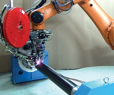
ISC via AFP. In-situ consolidated thermoplastic composites are typically made using automated fiber placement. This machine by MIKROSAM can process thermoset, dry fiber or in-situ consolidated thermoplastic composite materials, the latter most commonly built using laser heating. Photo Credit: MIKROSAM
MIKROSAM (Prilep, Macedonia) has developed a machine that can process thermoset or TPC structures, including in-situ consolidation. “We can achieve 98% consolidation and more than 30% crystallinity, depending on the materials,” says MIKROSAM sales director Dimitar Bogdanoski. “We have processed multiple TPC tape products, including those from Barrday, TenCate, Toho Tenax and Suprem.”
The machine can lay four or eight tapes/tows. “Any of the tows/tapes can be cut if you don’t need all of them placed,” says Bogdanoski, who claims an automated head change, from ATL to AFP (or vice versa) can be completed in 5 minutes. “AFP has a lower scrap rate vs. ATL due to the narrower material, so it is increasingly preferred. It’s useful to have this change capability to define which process is better for your part or project.”
Changing from thermoset to TPC takes about an hour, swapping the infrared (IR) heater used with thermoset materials to a 3-, 4- or 6-kW laser used with TPC — depending on the width of material that will be placed. “We can even use a 12-kW laser, but it requires a special license,” Bogdanoski notes. “The machine speed is between 5 m/min and 30 m/min for ISC parts, regardless if the material is PPS, PEEK or PEKK. We use an IR camera and an in-house developed thermal model, which forms a closed loop to control temperature of the laminate. It also incorporates video monitoring, which we developed in-house for quality assurance.” MIKROSAM sold one of these systems in 2016 and three in 2017.
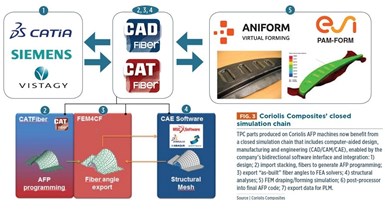
Coriolis Composites’ closed simulation chain. TPC parts produced on Coriolis AFP machines now benefit from a closed simulation chain that includes computer-aided design, manufacturing and engineering (CAD/CAM/CAE), enabled by the company’s bidirectional software interface and integration: 1) design; 2) import stacking, fibers to generate AFP programming; 3) export “as-built” fiber angles to FEA solvers; 4) structural analyses; 5) FEM draping/forming simulation; 6) post-processor into final AFP code; 7) export data for PLM. Photo Credit: Coriolis Composite
TPC parts produced on Coriolis machines now benefit from what the company calls a “closed simulation chain,” which integrates computer aided design, manufacturing and engineering (CAD-CAM-CAE) enabled by the company’s bidirectional software interface and integration. “The part begins with design by the OEM in CATIA [Dassault Systèmes, Velizy-Villacoublay, France],” says Hamlyn. “Our CAT/CADFiber software imports the composite stacking from CATIA and gives the user the tools needed to model all of the fibers. It then generates and optimizes the AFP tape/tow courses.”
After a test part is placed for validation, the software then exports true “as-built” fiber angles — including singularities such as tow drops and gaps due to use of narrow tapes, etc. — to commercial FEA solvers (e.g., NASTRAN, ABAQUS, SAMCEF) and enables mesh mapping between the AFP surface and the structural FEM mesh. Hamlyn says this reduces errors and facilitates data transfer as well as modeling of forming simulations. “This is the first step towards automating design optimization,” he asserts. “So now designers can perform structural analyses and crash simulations, interfacing with ANSYS [Canonsburg, PA, US].” The latter uses solid modeling instead of FEA shell elements for simulation of multi-ply composite laminates.
Next, physics-based FEM draping/forming simulations are performed, using programs like AniForm (Enschede, Netherlands) or ESI Group’s (Paris, France) PAM-FORM. “This includes intra-ply shear and fiber loading during forming, compaction and ply-ply slip,” notes Hamlyn. Thus, issues with wrinkles, gaps and fiber orientation during the transformation from 2D layup to 3D preform or part can be addressed and the preform contour can be optimized. He continues: “You then compare simulation results to real part trials to validate what is really happening. Once the design is frozen, our software interfaces with Dassault Systèmes’ DELMIA for machine simulation to check laying metrics and robot movements, ensuring that the AFP head can produce the part without collisions, etc. Once this is okay, our post-processor will transform the digital design into robot code, so the AFP machine will do exactly what you have simulated.”
“Factory of the Future”
This digital design and manufacturing chain and the automation already proven in large TPC aerostructure demonstrators align well with the Clean Sky 2 vision for future aircraft manufacturing, which is described as highly automated, flexible and based on functional integrated design. Thermoplastics also offer a means for attaining a multifunctional airframe, especially as the line between AFP and 3D printing dissolves. Clean Sky 2’s Platform 2 “Innovative Physical Integration Cabin – System – Structure” program includes large, integrated fuselage demonstrators. The Clean Sky 2 Joint Proposal Platform 2 key drivers are cost and weight:
“Without considering the engines, more than 50% of the recurring cost of manufacturing an aircraft is determined by the fuselage, the cabin and cargo equipment and the integration effort performed in the assembly of these components. .… considering a short-range commercial aircraft operating over 15 years, the reduction of just 100 kg of its original weight leads to more than 4 tons of fuel saving. Therefore, the potential of lighter and more efficient structures and systems for contributing to the ACARE vision 2020 [50% cut in CO2 emissions, which means 50% cut in fuel consumption for new aircraft in 2020], is enormous.”
By combining multiple airframe components into a much smaller number of integrated, TPC-based modules equipped with distributed power and systems, myriad parts, fasteners and holes are eliminated with a corresponding cut in machining and assembly operations. Clean Sky 2 proposes that potential weight savings could provide up to a double-digit reduction in fuel burn and a sustainable path to meeting future aircraft demand. Although there is still much to be developed and validated, thermoplastic composites seem destined to play a part in the aircraft factory of the future.
In Part 2, CW will explore issues with PEEK and PEKK materials and quality of tapes as well as the debate over a one-step vs. two-step process, all of which will impact how in-situ consolidation and thermoplastic composites play a part in future aircraft.
Related Content
Formula 1 team adopts Roboze 3D printed composites
The Visa Cash App RB Formula 1 team is collaborating with Roboze to reduce weight and create parts with complex geometries via carbon fiber/PEEK.
Read MoreEaton developing carbon-reinforced PEKK to replace aluminum in aircraft air ducts
3D printable material will meet ESD, flammability and other requirements to allow for flexible manufacturing of ducts, without tooling needed today.
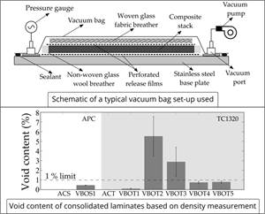
Read MoreTPRC research studies void removal mechanisms in VBO processing
New publication evaluates vacuum bag only-consolidated carbon fiber/PEEK tapes to determine the role of different void removal mechanisms in thermoplastic composites.
Read MoreHitachi Rail chooses Roboze printers, materials including carbon fiber/PEEK for railway spare parts
The Roboze ARGO 500 will be used at Hitachi Rail factories in Naples, Italy and Maryland, U.S. to reduce cost and delivery times for prototypes and spare parts.
Read MoreRead Next
Thermoplastic composite demonstrators — EU roadmap for future airframes
There is a TPC development roadmap in Europe, supported by Airbus and a variety of aerospace consortia, and involving almost every major aerostructures supplier in Europe.
Read MorePlant tour: Daher Shap’in TechCenter and composites production plant, Saint-Aignan-de-Grandlieu, France
Co-located R&D and production advance OOA thermosets, thermoplastics, welding, recycling and digital technologies for faster processing and certification of lighter, more sustainable composites.
Read MoreAll-recycled, needle-punched nonwoven CFRP slashes carbon footprint of Formula 2 seat
Dallara and Tenowo collaborate to produce a race-ready Formula 2 seat using recycled carbon fiber, reducing CO2 emissions by 97.5% compared to virgin materials.
Read More


