


Robotic winding of dry carbon fiber is used to make the central tube for a medium-class satellite (inset at right) and the Vega-C interstage 2/3 (left), reportedly the first resin-infused launcher structure to fly in a European Space Agency (ESA) mission. Source (All Images) | CIRA and ESA for Vega-C image
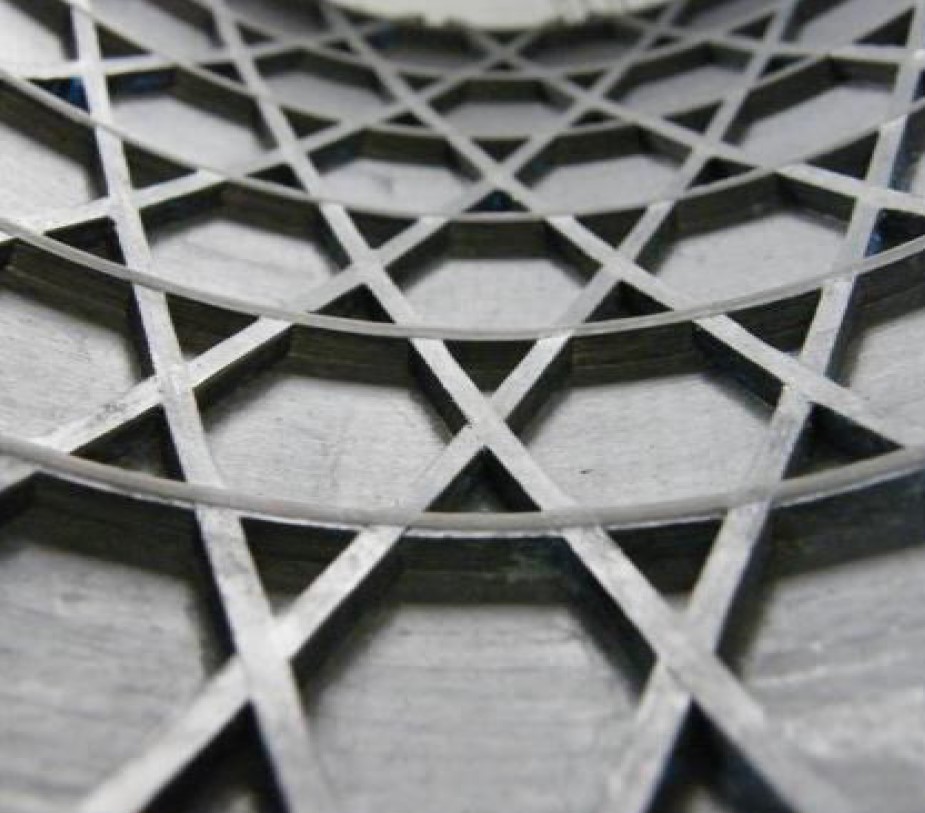
Anisogrid carbon fiber-reinforced polymer (CFRP) lattice shells are one of the most efficient designs to minimize mass in heavily loaded structures for space vehicles. They comprise a regular pattern of intersecting hoop and helical ribs (with or without a thin outer skin), providing both in-plane (membrane) and out-of-plane (bending) stiffness, essential to prevent buckling under high compressive loads.
In contrast, a homogeneous layered shell construction would provide in-plane stiffness but poor bending properties. This is why such shells are typically supported by additional structural elements, such as stringers, or use sandwich construction to improve stiffness. But this also adds weight, complexity and cost.


CFRP anisogrids have been made using wet filament winding since the 1980s and with automated placement of prepreg since the 1990s. However, wet winding — an open process using liquid resin — lacks the process control and precise resin content of prepreg. Meanwhile, placement of prepreg tapes results in buildup and fiber distortion in the nodes and requires dummy helical patterns to move between adjacent hoops. One solution is cutting the tows between hoops and selected nodes, the latter used by NLR to produce an orthogrid in the ACASIAS project (see “Integrating antennas into composite aerostructures”). However, this also interrupts the load path, reducing strength and increasing mass.
Over the last two decades, Centro Italiano Ricerche Aerospaziali (CIRA, Capua, Italy) has refined its design and manufacturing of CFRP lattice structures, moving through prepreg and wet winding as well as improved design analysis. By 2009, it had patented a “parallel winding” technique with dry fiber followed by resin infusion. The result is an interlaced anisogrid with uncut, continuous tows and without dummy helical patterns.
This process developed by CIRA is clean, extremely efficient and scalable, ranging from very thin to very thick ribs (cross-section of 4-400 square millimeters). It has been used by Avio (Colleferro, Italy) to produce the interstage 2/3 for the Vega-C space launcher, first flown in 2022. Since then, CIRA has further demonstrated this method’s scalability, producing a large central tube and long instrument boom for satellites and a conical payload adapter for launchers.
Parallel winding
“So many methods have been proposed in the last decades to manufacture interlaced lattice structures,” says Dr. Felice De Nicola, head of the CIRA Composite Prototyping Lab. “We were looking to produce something which was integral, simple and low cost. We also wanted to overcome the problems with wet winding and prepreg by using resin infusion, which is a very simple technique.”

CIRA’s patented parallel winding process uses robotic winding to create helical ribs while a creel simultaneously interlaces hoop ribs (and wider “black rings” for attachments) without cut tows or dummy helical patterns. Resulting anisogrids have at least 20% less mass and better compressive strength than composite sandwich or skin-stringer construction for the same structures.
CIRA creates the anisogrid’s interlaced hoop and helical ribs using a robotic cell, which implements a refined version of filament winding in conjunction with a patented approach called parallel winding. “We use helical winding around pins simultaneously with hoop winding applied in parallel from a creel off to the side of the rotating mandrel,” says De Nicola. “The dry fiber ribs are thus interlaced using a very simple setup, which can guarantee fiber straightness, but is also a reasonably fast process.”
This also eliminates the need to cut tows or use a dummy helical rib pattern. “If you have just one deposition head, like in filament winding,” he explains, “then you must have additional helicals to enable moving between adjacent hoop paths. But because we wind the hoops by a separate mechanism, we avoid this issue.”
Silicone rubber sheets, metal pins for winding
The winding is applied to a metal mandrel covered with a silicone rubber “carpet” or sheet. De Nicola notes this eliminates the need to place hundreds of triangular or hexagonal Teflon or silicone inserts, an approach proposed by other groups. “In contrast, our production of the reusable sheet is simple, using a well-proven technique,” he says. “We use liquid silicone casting on a machined aluminum mold. The resulting shape provides a sheet mold with grooves into which the dry fibers are placed.”


CIRA uses liquid silicone casting to create sheet molds (top) that are wrapped around an aluminum mandrel, providing grooves into which dry fibers are wound for the antenna boom shown here. Metal pins in the mandrel at both ends of the sheet enable helical windings (applied by robot at left side of right image) without cutting fibers. Note: Hoop ribs are being wound from a creel off to the right of the mandrel.
More recently, the group used 3D printing of a small modular element to avoid a large machined mold. “In this case, the mold was very simple — just a sector of a cylinder,” says De Nicola. “We then cast multiple sectors and joined them by using the same liquid silicone rubber, creating a single cylindrical sheet mold.” He concedes that this approach requires ≈100 kilograms of silicone rubber for medium-sized structures, “which is not cheap; but it is more cost-effective than making and placing hundreds of silicone rubber triangular inserts.”
CIRA’s use of pins in the helical winding is also an adaptation of established techniques. “Pins have long been used in filament winding,” says De Nicola. For example, they enable winding around an open-ended structure without cutting fibers. “In our case, they are concentrated just where the ribs are. So, we only have a small number of pins on the mandrel to the left and right edge of the silicone rubber sheet. It’s quite simple. But you do need to have maneuverability in the robotic head to wrap around the pins. Once winding, infusion and curing are complete, we simply unscrew the pins from the mandrel.”
Materials and resin infusion
The completed dry preform is then vacuum bagged and infused with resin. “We typically use intermediate modulus carbon fiber,” says De Nicola. “But we’ve also used high modulus for booms and applications where the stiffness and thermal expansion were key factors.” Suppliers have included Toray (Tokyo, Japan), Hexcel (Stamford, Conn., U.S.) and Teijin (Tokyo, Japan). He notes dry fibers are more fragile than prepreg. “So, the winding system must manage the fibers properly and maintain tension without damage during application.”
Regarding resins, CIRA researcher and materials specialist Dr. Gionvangiuseppe Giusto explains that sufficiently low viscosity (e.g., ≈200 centipoise) is needed to fully infiltrate the fibers especially at the nodes where the ribs cross. “We usually prefer epoxy systems,” he says, “but for specific applications, such as satellite booms where temperatures range from -160 to 160°C, we have used cyanate ester.” CIRA has also used resins from Huntsman (The Woodlands, Texas, U.S.), Syensqo (previously Solvay, Heanor, U.K.) and Hexcel. “We consider a range of resins and then select based on Tg and process parameter specifications,” says Giusto. “We typically start with resins already qualified for space applications, but in certain applications, we have proposed an epoxy used mainly in automotive applications.”
During infusion, a standard distribution medium facilitates resin flow throughout the preform. “We use commercially available polymer mesh products from Airtech [Huntington Beach, Calif. U.S.],” says Giusto, “usually formulated for high temperature.”
Paola Spena, materials and process specialist at CIRA, notes that the resin runs quite fast between the nodes where the fiber volume fraction is lower. “It then slows at the nodes, which require a little bit more time to be filled. But the flow medium helps, and this is an advantage of resin infusion compared to resin transfer molding [RTM] processes. In RTM, you are using pressure to push the resin front horizontally through the preform, which can take a long time for a large part. To reduce this, RTM often uses multiple resin injection inlets. In vacuum-assisted infusion, the flow medium not only speeds the resin across the preform but also helps it to penetrate in the Z direction or thickness. So, we use just one resin inlet.”
“We have that inlet at the bottom of the structure and learned that vertical infusion is the simplest for us,” adds Giusto. “Infusing against gravity facilitates removal of air, volatiles and bubbles that otherwise could be entrapped. It also almost unites the flow fronts across the ribs and the flow proceeds rather evenly — so, we no longer use flow modeling. With the distribution medium, the resin quickly permeates the ribs, even when using a relatively thicker skin, such as in the Vega-C interstage, for example.”
“It is quite easy for us to infuse these anisogrids,” says Spena, “even a structure that is 3-4 meters tall. Infusion takes about 1 hour for a 2-meter-diameter, 2.5-meter-tall satellite central tube, for example. And our preforms are sort of optimized for this process. Obviously, the infusion flow will be a little bit slower through the higher mass of fiber in a 2-millimeter-thick skin, but it also produces a very good, compacted laminate.”

CIRA prepares a conical adapter for oven cure after resin infusion.
After infusion is complete, CIRA uses an autoclave or oven for cure depending on the resin and part requirements. “We have used out-of-autoclave [OOA] curing for boom and satellite central tube structures,” says De Nicola. “The idea is to get away from the autoclave and have a more cost-effective process. And we achieved a regular cross-section along the ribs and also through the nodal regions, without distortions.”
This was important to demonstrate that CIRA’s approach can indeed produce high-performance structures, he says, “and yet maintain simplicity, because we were looking for efficiency — not only in terms of mass, but in terms of process as well. We believe the Vega-C interstage was the first heavily loaded launcher structure to be made by liquid infusion for an ESA project in Europe.”
Lower fiber volume and mass, higher compressive strength
CIRA’s approach provides a complete preform with interlaced ribs, but the fiber volume fraction in the ribs is lower than conventional aerospace laminates. “We achieve a fiber volume fraction of 34-40%, compared to the more standard 50% plus,” says Dr. Giovanni Totaro, CIRA researcher and the primary design engineer for this technology. “Ours is lower, but this allows more resin which then boosts specific compressive properties. Meanwhile, our mass density will be about 1,400 kilograms/cubic meter versus 1,600 kilograms/cubic meter for standard constructions. The drawback is that we don’t have the maximum stiffness because the fiber volume fraction is not maximized. But we do maximize specific compressive strength, which then helps us to to reach an optimized structure under compressive loads.”
“This emphasizes the efficiency of our approach in applications that are driven by strength and buckling,” says Totaro. “In addition, the anisogrid’s unidirectional [UD] ribs exhibit a very low coefficient of thermal expansion [CTE] in the longitudinal direction driven by the carbon fiber, which offers benefits for applications demanding dimensional stability in extreme thermal conditions, such as antenna booms.”
“The anisogrids we are producing are cylinders and cones that are heavily loaded in compression, and their design is driven by buckling,” says De Nicola. “For the situation in which the design is completely dominated by stiffness, our anisogrid structures are still competitive but they probably won’t be the most efficient design.” But Totaro notes that CIRA also achieves at least 20% lower mass compared to composites made with skin-stringer or sandwich constructions for the same structures.
More efficient anisogrid optimization
CIRA has not only developed an approach for more efficient anisogrid manufacturing, but also a more efficient method for optimized designs. Led by Totaro, CIRA began by looking at specific models for local in-plane buckling. “This occurs, for example, in the larger radius of conical structures. Conventional out-of-plane buckling occurs in the transverse or radial direction,” he explains. “The latter was already described, but in-plane buckling was only described with a simplified approach. We thus developed and validated more accurate in-plane modeling which provides more structurally efficient solutions.”
He also ended up with a more efficient overall design process. “Anisogrid structures may use a wide range of design configurations,” says Totaro. “We needed to explore all the lattice configurations for a certain geometry — e.g., a cylinder or cone — and for each, identify the best cross-section of ribs to minimize the lattice mass without local buckling. We also had to meet global buckling requirements as well as overall structural stiffness and strength requirements.” The resulting process comprises three main phases.


CIRA’s three-phase design optimization method explores anisogrid parameters (top) to downselect best configurations for simple finite element (FE) analysis, which outputs the best configuration for final 3D CAD stress analysis (bottom).
1. Parametric exploration. Each possible design configuration for a cylinder or cone is defined by a certain number of regularly spaced hoop and helical ribs. This also defines the helical angle, which is the fundamental design variable. Each configuration is further characterized by the thickness and width of hoop and helical ribs.
“We have a sort of parametric exploration of design configurations, and for each configuration, we identify minimal mass options,” says Totaro. “Basically, we perform a large parametric study to identify the whole design space. Because we are dealing not with finite element [FE] models in this phase, but just with equations and gradient-based optimization algorithms, we can get the overall picture of the possible configurations in a few minutes.”
This analysis uses a constrained minimization routine in the Matlab Optimization Toolbox software (MathWorks, Natick, Mass., U.S.). The objective is to minimize the grid shell mass, and constraint equations are represented by analytical models, which approximate the stiffness properties and the various failure mechanisms of the structure. Each configuration is separately optimized. “Specific analytical models are then formulated for the anisogrid’s system of hexagonal and triangular cells, allowing us to identify buckling mechanisms and understand the role of hoop ribs which was earlier underrated,” says Totaro. “We also analytically formulated pocket buckling of the skin, which occurs in the hexagonal pockets and will propagate along the structure. It also drives the optimal stacking sequence of a skin laminate.” These models are typically formulated using Maple software (Maplesoft, Waterloo, ON, Canada).”
2. Simple FE models. Once best candidates for minimum mass are identified, they are transformed into FE models made of simple 1D “bar” elements for the ribs and 2D elements for the skin, if one is being used. “These can be automatically generated in a few minutes,” says Totaro. “The goal is just to verify that the expected stiffness and strength performance is reasonably achieved with the possibility to easily adjust the cross-section of ribs or the stacking sequence of the skin, and finally to refine the solution.” This process is relatively quick, based on specific routines which builds the input file for the Nastran solver (available from multiple suppliers). “We then conduct the more refined analyses and downselect again,” says Totaro. “This phase ends with the final configuration and cross-section of ribs.”
3. Final 3D models. This final design is then transformed into a 3D CAD model, which is the fundamental input for production of the tooling and defining the manufacturing process (mandrel, molds, interfaces) as well as the construction of the final 3D FE model for the detailed stress-strain analysis. In this final phase, all of the material properties and the additional structural elements that were initially excluded from the previous simplified versions are brought into the FE model and analyzed.
Thus, high-computation time analyses are minimized and reached quickly by a simplified downselection process, but one that still considers the most important performance factors for anisogrid structural behavior.
“This years-long development by Totaro has provided CIRA with a very good knowledge of analytical models for anisogrids,” says De Nicola, “but also a very fast process. The models are sophisticated, but also in semi-analytical forms, so software can return initial optimization results quickly and we can then refine these using standard FE methods. From the beginning, we strove to include real knowledge of the behavior of the anisogrid structure, which isn’t typical. Instead of having a general model with general elements to be optimized, we have a specific knowledge of the lattice structure behavior. Again, this leads us to new designs that offer new opportunities for lightweight and efficiency.”
Demolding
After resin infusion and cure, extracting the mandrel is typically not an issue for conical structures or large cylinders, says De Nicola. “We can have difficulty with long, thin cylinders like booms. For these, you need a mechanical extractor device to remove the mandrel, but it is usually extracted without applying high loads. For longer structures, where the friction is higher, we use a Teflon layer between the silicone rubber mold sheet and the aluminum mandrel.”
The aluminum mandrel’s expansion during cure helps to consolidate the part and its contraction during cooling also helps demolding. De Nicola notes the silicone rubber sheet tool on top of the mandrel has an even higher thermal expansion, and that also compacts the material during cure. “We factor in that expansion to correctly dimension the composite ribs.”

Finished CFRP anisogrid boom structure.
Once the parts are extracted, the peel ply is removed to reveal high-quality finished surfaces. For composite anisogrids without a skin, the cured resin film in the spaces between ribs is easily removed. “It is very thin — a few tenths of a millimeter,” says De Nicola, “and it’s distributed all over the surface, but you can cut or knock it away in minutes.”
Increasing number of applications
CIRA has demonstrated the capability and versatility of its design and manufacturing approach, from large to small structures. The 2.4-meter diameter, 2-meter-long interstage 2/3 for the Vega-C space launcher was a key demonstration. “It took 3 weeks for us to wind the very first Vega-C interstage prototype,” says De Nicola. “We then worked with Avio to mature and speed up the process, and after successfully completing testing in 2018 — including bending stiffness evaluation and compression loading up to 750 tons — Avio then produced the certification parts.”
Vega-C first flew in 2022 but missions were paused after the second launch, due to a failure in the nozzle of the Zefiro motor. Vega-C is scheduled to resume flights later in 2024 with an intense program of launches for 2025.


CIRA has also produced a 0.64-meter-long, 1.4-meter-diameter conical adapter that weighs only 7 kilograms — 30% less than the reference CFRP solution — yet can withstand 80 tons of compressive load. The structure includes 70 fiber bragg grating (FBG) sensors embedded in the helical ribs during the deposition process to show the feasiblity of integrating a structural health monitoring (SHM) and sensing system. “This system worked very well during the mechanical testing campaign,” says Totaro, “providing a fine coverage of strain sensors used to better understand the structural behavior and to validate the detailed FE model of the structure.”
Another application, CIRA’s 1.2-meter-diameter, 2.7-meter-long prototype of a central tube main structure for a medium-class satellite, not only balanced stiffness and strength requirements but achieved a specific mass <14 kilograms/meter — a 20% savings versus traditional composite shell structures.

Wound in the hoop direction, black rings are wider than hoop ribs and provide attachment points for bolted connections.
Here, parallel winding was used to integrate “black rings” — hoop ribs with larger width and fibers in two directions to provide bearing strength for bolted connections. “These rings are typically introduced along the edges of shell structures as interfaces with flanges for adjacent components,” says Totaro. “They are also integrated into the structure wherever local reinforcement for attachment points are needed. We have the flexibility to integrate black rings with the same height (radial thickness) as the ribs, or with reduced depth (e.g., half radial thickness or less) in order to save mass.”
CIRA’s most recent demonstration is a slender 120-millimeter-diameter, 1.5-meter-long CFRP anisogrid boom segment for a deployable satellite antenna. Its design was dominated by requirements for thermal dimensional stability and a high stiffness-to-weight ratio. CIRA used thin ribs — cross-section of 1.5 × 3.6 millimeters — achieving a specific mass of 0.5 kilograms/meter. “To achieve a similar mass with a homogeneous skin,” notes Totaro, “the laminate thickness would need to be 1.0 millimeter or less, making it more difficult to achieve the ideal stacking sequence to meet combined stiffness, CTE and strength requirements.”
“Again, there is no distortion in the UD fiber paths and no buildup at the nodes because we use dry fiber instead of prepreg,” says De Nicola. “The interlacing also results in structures that are extremely damage tolerant for their mass. The combination of our more efficient design method with our manufacturing approach makes composite anisogrids a more practical solution, not just for space vehicles but for a much broader range of aerospace applications. We see a huge potential and are continuing development toward even lighter and more efficient composite structures in the future.”


Related Content

On the radar: Cryogenic testing of composites for future hydrogen storage
Netherlands, U.K., France, Germany and the U.S. build up test capability, look at thermoset and thermoplastic composite materials.
Read More
Rocket Lab begins installation of large AFP machine for rocket production
The 99-ton AFP machine, custom-designed and built by Electroimpact, is claimed to be the largest of its kind, expecting to save around 150,000 manufacturing hours in the Neutron rocket’s production process.
Read More
High-temperature composite 3D printing facilitates design, manufacture of deployable space structures
Opterus R&D employs an AON3D printer and OOA prepregs to build the tooling, prototypes and end-use versions of its foldable CFRP satellite structures.
Read More
Nanomaterials optimize performance of space-ready carbon fiber composite panels
A recent ESA project led by Adamant Composites aimed to mature nanomaterial-enhanced CFRP for lighter weight, more thermally and electrically conductive materials for manufacturing satellite structures.
Read MoreRead Next

Filament winding increases access to high-performance composite prostheses
Steptics industrializes production of CFRP prostheses, enabling hundreds of parts/day and 50% lower cost.
Read More
Optimized rib-reinforced hollow composites via printed molds
Addyx topology optimization and water-soluble mandrel enables simultaneous rib and skin layup for one-shot, high-strength, lightweight structures.
Read More
Drawing design cues from nature: Designing for biomimetic composites, Part 2
As biomimetic design continues to inform composites manufacturing, technologies like 3D printing, tailored fiber placement, braiding and filament winding prove strong candidates for making these structures a reality.
Read More