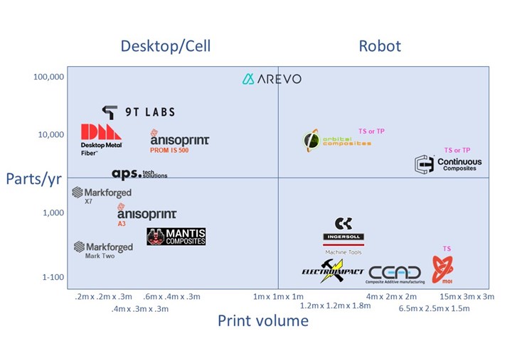
3D printing with continuous fiber landscape of suppliers technologies. Photo Credit: CW
As the list of companies commercializing continuous fiber 3D printing continues to grow, so does the spectrum of materials, processes, parts sizes, production volumes, applications and end markets. To get a picture of the current landscape, CW recently polled companies which have developed technology in this space and produced the above graphic to help put this technology in context.
Classification of processes
Typical for composites, technology development in continuous fiber printing is fluid and fast-paced, resulting in myriad new terms (and acronyms). Alexander Matschinski, research associate and expert for Additive Manufacturing at TU Munich and the Chair for Carbon Composites (LCC), recently presented his effort to standardize concepts for the direct integration of continuous fiber in 3D printing processes (Fig. 1). “Due to the company-specific nuances in how these processes are implemented, categorization is difficult,” he concedes. “But there are some trends, especially if we focus on how the fiber and matrix are brought into the print nozzle and how they are deposited.”
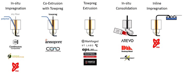
Fig. 1. Concepts for direct fiber integration. Information source: Alexander Matschinski, Virtual Symposium on AFP and AM, TU Munich, Chair of Carbon Composites (LCC), Sep. 2020.
In-situ impregnation. Dry fiber is fed into the nozzle while a matrix material is injected through one or more inflows during deposition by co-extrusion. The matrix is thus introduced, heated and in-situ impregnates the fiber prior to being deposited.
Co-extrusion with towpreg. Instead of dry fiber, towpreg/thin prepreg tape is fed into the nozzle, heated and co-extruded with additional matrix material. Typically, the matrix in the towpreg is identical to that in the co-extrusion. An exception is Anisoprint, where the towpreg matrix is thermoset and the coextrusion is thermoplastic.
Towpreg extrusion. The towpreg input is heated and extruded without any additional material.
In-situ consolidation. Essentially a scaled-down version of thermoplastic automated fiber placement (AFP) where the input thermoplastic towpreg/prepreg tape is consolidated in-situ when deposited. The feedstock is heated by an external energy source at the nozzle during the feeding process and is then placed and consolidated by a pressure roller during deposition.
Inline Impregnation. The fiber is impregnated while it is transported into the print head, similar to 3D filament winding. As with towpreg extrusion, the deposition takes place via a nozzle.
Several additional terms are helpful to understand technology nuances below. Towpreg extrusion is commonly described as fused deposition modeling (FDM), a term trademarked by Stratasys (Eden Prairie, Minn., U.S.). In the 3D printing industry, fused filament fabrication (FFF) denotes printing with a spaghetti-like strand of polymer called a filament and is used interchangeably with FDM. Thus, FFF can describe printing with filament that is unreinforced, chopped fiber-filled or continuous fiber-reinforced. Continuous filament fabrication (CFF), however, specifically denotes printing with continuous fiber reinforcement.
Desktop/cell
9T Labs’ (Zurich, Switzerland) two-step Red Series technology includes a Build Module for layup and Fusion Module for consolidation of carbon fiber-reinforced PEKK (polyetherketoneketone) and PA12 (polyamide) materials. It is developing AFP-like deposition with infinite rotation, and its strategy to produce relatively high volumes of high-performance parts is demonstrated in its partnership with advanced metal parts manufacturer Setforge (L’Horme, France).
Anisoprint’s (Esch-sur-Alzette, Luxembourg) twin-nozzle Composite Fiber Co-extrusion (CFC) technology uses one nozzle for FFF and one for co-extrusion with carbon or basalt towpreg made using a range of thermoplastics from PLA (polylactic acid) to PEEK (polyetheretherketone).
Desktop Metal’s (Burlington, Mass., U.S.) Fiber printers, launched in 2019, use a robotic tool changer to switch between FFF and μAFP (micro AFP) deposition heads. LT models print with carbon (CF) or glass fiber (GF) and PA6, while HT models also print in PEEK and PEKK.
APS Tech Solutions (Höchst, Austria) uses CFF featuring an integrated inline cutting mechanism and automated tool-changing system with four printheads: CFF-printhead for CF with PA or PEEK, GF, aramid fibers (AF) and copper wires; or FFF-printheads for a variety of materials including PLA, ABS (acrylonitrile butadiene styrene), PEEK and metals/ceramics for sintering applications.
Markforged’s (Watertown, Mass., U.S.) twin-nozzle Continuous Fiber Reinforcement (CFR) technology augments FFF by using a CFR nozzle to lay down continuous CF, GF or AF and PA into an FFF-printed part. The company builds both desktop and industrial 3D printers.
Robot/cell hybrids
Arevo’s (Santa Clara, Calif., U.S.) direct-to-consumer Superstrata eBikes serve as a demonstrator for its direct energy deposition (DED) machines, which are based on continuous carbon fiber and thermoplastics including PA, PEEK and PEKK. Its robot-based printing in an enclosed cell achieves true 3D paths and z-direction reinforcement.
CEAD’s (Delft, Netherlands) Continuous Fiber Additive Manufacturing (CFAM) Prime cell is gantry-based, while its AM Flexbot is robot-based. Both combine pellet extrusion with unidirectional (UD) tapes. The company recently printed a GF/PET (polyethylene terephthalate) bridge, including chopped and continuous fibers, with Royal HaskoningDHV (Amersfoort, Netherlands) and DSM (Heerlen, Netherlands), and will soon launch even larger versions of its systems.
Mantis Composites (San Luis Obispo, Calif., U.S.) uses an FFF type process with a five-axis machine for true 3D placement of complex parts for space and aircraft applications. It uses mostly carbon fiber and high-performance thermoplastics such as PEEK, though materials vary per customer and part requirements.
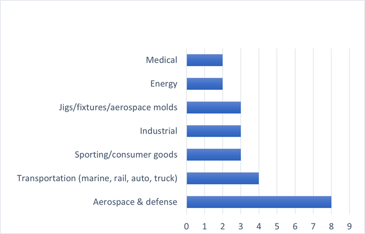
Fig. 2. Top targeted markets. Based on responses to CW poll of 13 companies supplying continuous fiber 3D printing technology.
Robotic 3D printing
Continuous Composites’ (Coeur d'Alene, Idaho, U.S.) Continuous Fiber 3D Printing (CF3D) system impregnates continuous dry fiber in-situ with liquid thermoset resin in a print head, discharging a wetted tow, which is consolidated prior to snap-polymerization by a high-intensity cure source. It uses various dry continuous fibers — including wires and fiber optics — and snap-curing resins developed in partnership with Arkema (Colombes, France) and its Sartomer subsidiary.
Electroimpact’s (Mukilteo, Wash., U.S.) SCRAM system integrates a dexterous in-situ consolidation AFP head with two FFF nozzles, one to print support tooling and the other to print with unreinforced or chopped fiber filament. This multifunctional manufacturing cell will soon integrate pellet extrusion and CNC milling, aiming to change how aerospace and defense parts are designed and manufactured (see “Combining AFP with 3D printing for flexible parts production”).
Ingersoll Machine Tools’ (Rockford, Ill., U.S.) multi-axis robotic MasterPrint Continuous Filament printers use co-extrusion of thermoplastic neat filament and towpreg to create complex 3D shapes and continuous fiber reinforcements on existing structures through overprinting. Options include an external axis turntable and additional nozzle for printing support and locating structures.
moi composites’ (Milan, Italy) Continuous Fiber Manufacturing (CFM) technology uses inline impregnation or towpreg extrusion for a variety of continuous fiber and thermoset resin combinations. Its largest print to date is the 6.5-by-2.5-meter MAMBO (Motor Additive Manufacturing BOat), printed in GF and vinyl ester with partners including Autodesk, Owens Corning and Catmarine shipyard.
Orbital Composites’ (San Jose, Calif., U.S.) ORB 1 system can use in-situ impregnation and FFF nozzles to process PA, PEI, PPS and PEEK as well as thermosets reinforced with CF (3K to 100K tow), GF, metal wires and fiber optics. The modular platform allows easy scalability and multiple larger systems are in development.
Related Content
Jeep all-composite roof receivers achieve steel performance at low mass
Ultrashort carbon fiber/PPA replaces steel on rooftop brackets to hold Jeep soft tops, hardtops.
Read MorePlant tour: Albany Engineered Composites, Rochester, N.H., U.S.
Efficient, high-quality, well-controlled composites manufacturing at volume is the mantra for this 3D weaving specialist.
Read MorePultrusion: The basics
A primer describing what pultrusion is, its advantages and disadvantages, and typical applications.
Read MoreManufacturing the MFFD thermoplastic composite fuselage
Demonstrator’s upper, lower shells and assembly prove materials and new processes for lighter, cheaper and more sustainable high-rate future aircraft.
Read MoreRead Next
VIDEO: High-volume processing for fiberglass components
Cannon Ergos, a company specializing in high-ton presses and equipment for composites fabrication and plastics processing, displayed automotive and industrial components at CAMX 2024.
Read MoreAll-recycled, needle-punched nonwoven CFRP slashes carbon footprint of Formula 2 seat
Dallara and Tenowo collaborate to produce a race-ready Formula 2 seat using recycled carbon fiber, reducing CO2 emissions by 97.5% compared to virgin materials.
Read MoreDeveloping bonded composite repair for ships, offshore units
Bureau Veritas and industry partners issue guidelines and pave the way for certification via StrengthBond Offshore project.
Read More

.jpg;width=70;height=70;mode=crop)


